| Electrode name | Electrolytic cell type | Electrolyte | CO2 flow velocity | Reference electrode | iR compensation | Ref |
|---|---|---|---|---|---|---|
| Cu hetero-interface electrode | H-type cell | 0.1 M KHCO3(CO2 saturated,30 mL) | 20 mL/min(750 r/min) | Ag/AgCl(Converted to RHE) | 85% | 26 |
| CuOx soft-landed catalyst electrode | H-type cell and gas diffusion electrode | 0.1 M or 1 M KHCO3(CO2 saturated,circulation volume 4~5 mL) | H-cell:persistent bubbling;Flow cell:5~7.5 sccm | Ag/AgCl(Leakage type, converted to RHE) | -(Not explicitly stated in the text) | 24 |
| Cu-polymer composite electrode | Flow cell | 1 M KOH(0.7 mL/min) | 12 sccm | Ag/AgCl(3 M KCl,converted to RHE) | - | 46 |
| Nanoporous Cu cathode (CO2-triggered break-in) | Zero-Gap MEA Electrolyze + Three-Electrode Half-Cell Testing | half-cell:0.1 M KOH / 0.5 M KHCO3;MEA:Anode 0.05 M KOH | MEA: cathode 50 sccm wet CO2, anode 15 sccm KHCO3 | Half-cell:Hg/HgO;MEA:Full Battery Test | - | 47 |
| Highly porous Cu catalyst | Microfluidic flow Electrolyze | 1 M KOH、1 M KHCO3、1 M KCl、1 M K2SO4 | - | RHE | - | 48 |
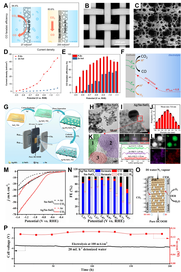
| Porous Zn catalyst electrode | H-type cell and gas diffusion electrode | H-cell: 0.1 M KHCO3;Flow-cell: 1.0 M KHCO3 or 1.0 M KOH | H-cell: 21 mL/min;Flow-cell: 40 mL/min | Ag/AgCl(3 M NaCl,converted to RHE) | 85% | 4 |
| AgSn-SnO2 nanosheet electrode | H-type cell and gas diffusion electrode | H-cell: 0.5 M KHCO3;Flow-cell: 1.0 M KOH;Solid electrolyte: Anode 0.1 M H2SO4,Cathode CO2 gas | H-cell: 20 sccm;Flow cell: 20 sccm;Solid: 30 sccm | H-cell/Flow cell: Ag/AgCl;Solid: two-electrode system | - | 18 |
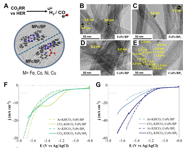
| M-Pc/Buckypaper composite electrode | H-type cell | 0.5 M KHCO3(CO2/Ar saturated) | 15 mL/min(20 min) | Ag/AgCl(saturated KCl,Luggin capillaries) | 85% (positive feedback) | 60 |
| Biomass-derived carbon aerogel electrode | H-type cell | 0.1 M KHCO3(CO2 saturated,pH≈6.8) | 10 mL/min(30 min) | Ag/AgCl(saturated KCl,Luggin capillaries) | 85% (positive feedback) | 23 |
| 3D printed metal-free carbon electrode | H-type cell | 0.1 M KHCO3(CO2 saturated) | Persistent bubbling | SCE(saturated calomel electrode) | - | 21 |
| 3D printed fluoropolymer GDL electrode | Flow cell | 1 M KHCO3 | 50 sccm | Ag/AgCl(converted to RHE) | - | 13 |
| Imidazolium-functionalized GC electrode | Liquid-phase three-electrode cell + flow-through electrolytic cell (GDE) | Liquid phase:0.5 M [EMIM][BF4]/[PF₆];Flow: Acidic aqueous solution | - | Ag/AgCl(Complemented by Fc⁺/Fc internal markers) | - | 12 |
| Bi@C/Si nanowire photocathode | H-type photoelectrochemical cell (quartz cell, separated by Nafion 117 membrane) | 0.1 M KHCO3(CO2 saturated) | 99.99% CO2, 30 min | Ag/AgCl | - | 9 |
| CNT/Graphene-PPS flexible film electrode | Three-electrode system | 0.5 M Na2SO4(pH≈6)0.5 M PBS(pH 7, 8) | - | SCE(converted to RHE) | - | 20 |
| 3D Graphene-CNT hybrid with Co-MnO NPs | Three-electrode system | 0.1 M KOH 0.1 M H2SO4 | - | RHE | - | 22 |
| Ni-Co sulfide/graphene-CNT composite electrode | Three-electrode system | 6 M KOH | - | Hg/HgO | - | 65 |