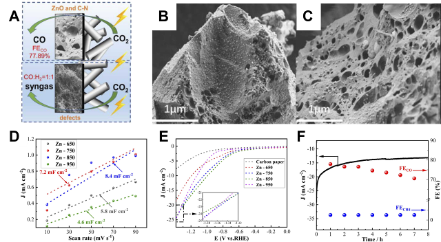
Fig. 5 Carbon aerogel versus carbon foam electrode constructs: (A) Schematic representation of the active sites of Zn-750 and Zn-950. (B) SEM images of Zn-650 and (C) Zn-750. (D) ECSA curves and (E) LSV curves of Zn-T. (F) FE stability of Zn-750 after 8 h of continuous operation at −1.0 V vs. RHE[23]
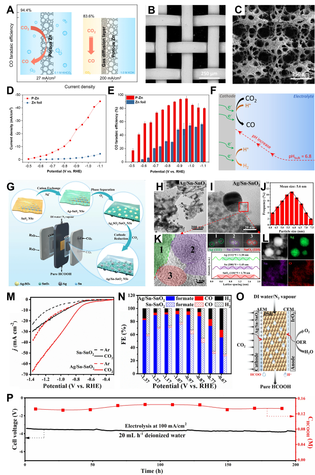
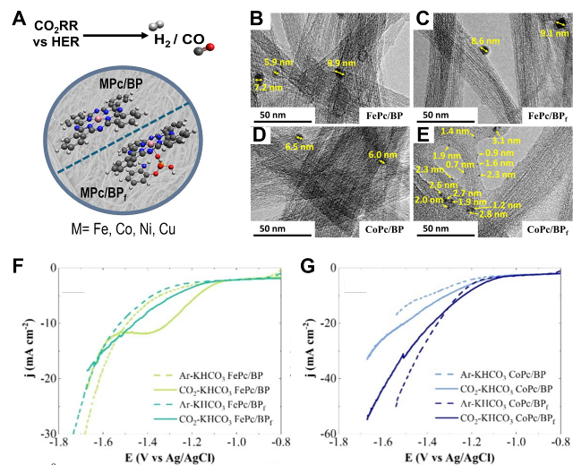
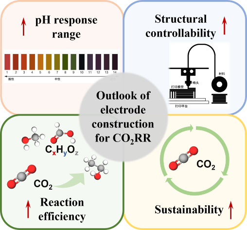
Other figure/table from this article