


1 引言
表1 常用聚合物基体优缺点对比Table 1 Comparison of advantages and disadvantages of common polymer matrix |
| Polymer matrix | Advantages | Disadvantages |
|---|---|---|
| PEO | High safety, good electrochemical stability, low price, good film forming property | High crystallinity and low room temperature ionic conductivity |
| PAN | High thermal stability and ionic conductivity | Poor mechanical properties, brittle after film formation |
| PVDF | High safety, dielectric constant and oxidation resistance | Poor mechanical properties, low ionic conductivity |
| PVP | Good film forming and chemical stability | Poor mechanical properties, brittle after film formation |
| PMMA | Good interface stability and low price | High crystallinity, Poor mechanical properties and low ionic conductivity |
2 PEO基聚合物固体电解质
2.1 PEO的物理化学性质
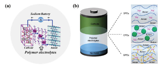
2.2 PEO聚合物固体电解质
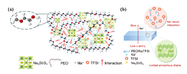
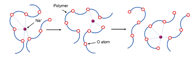
2.3 离子传输机制
3 PEO基聚合物固体电解质制备方法
3.1 溶液浇铸法
3.2 热压法
3.3 其他方法
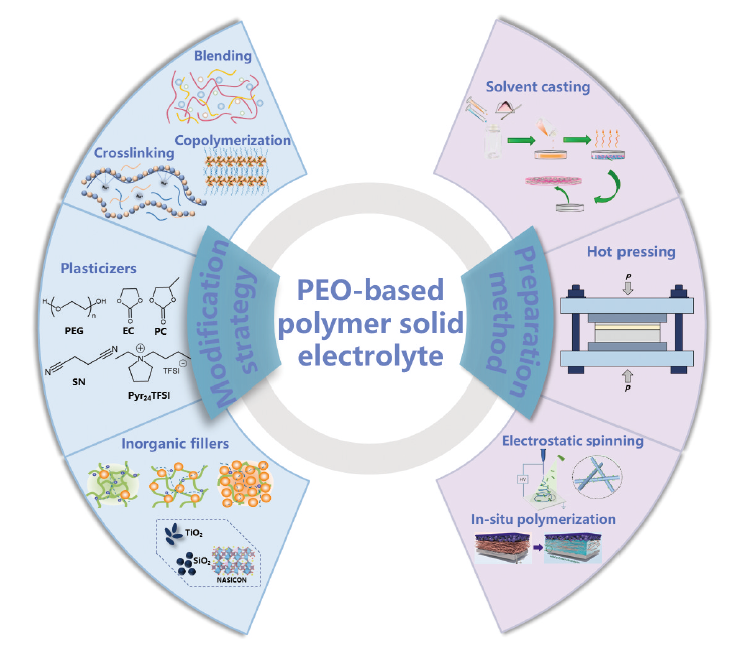
4 改性策略
4.1 聚合物共混、嵌段共聚、交联
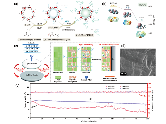
图4 (a)21-β-CD-g-PTFEMA新型聚合物的合成路径[49];(b)密度泛函理论(DFT)分析最高占据分子轨道(HOMO)和不同聚合物单元的电子云密度分布概率[49];(c)非晶态PPC和NASICON颗粒掺入结晶PEO基体中的CPE优化示意图[51];(d)Na-CMC为骨架的三维交联结构SPE的高倍FESEM[55];(e)Na|SPE|Na3V2(PO4)3电池在1 C倍率下的比容量和库仑效率曲线[56]Fig.4 (a) Synthetic route for 21-β-CD-g-PTFEMA[49]; (b) Density functional theory (DFT) analysis of the highest occupied molecular orbital (HOMO) and probability of electron cloud density distributions for different polymer units[49]; (c) Schematic of the optimizing steps for amorphous PPC and NASICON particles incorporated into the crystalline PEO host[51]; (d) FESEM analysis at high magnification of the three-dimensional cross-linked structure SPE with Na-CMC as the skeleton[55]; (e) Specific capacity and coulombic efficiency curves of Na|SPE|Na3V2(PO4)3 battery cycled at 1 C rate[56] |
表2 基于聚合物共混、嵌段共聚、交联改性固体电解质离子电导率对比Table 2 Comparison of ionic conductivity of solid electrolyte modified by polymer blending, block copolymerization and cross-linking |
| Electrolyte | Test temperature/℃ | Conductivity/ S·cm-1 | Electrode | ref |
|---|---|---|---|---|
| PEO/PVP/NaPO3 | RT | 1.07×10⁻⁵ | Na‖(C + I2 + Electrolyte) | 48 |
| PEO/ASPE | 80 | > 10-4 | Na‖Na3V2(PO4)3 | 49 |
| PEO/PVDF/NaClO4/TiO2 | RT | 8.75×10⁻⁵ | — | 50 |
| PEO/PPC/NASICON | 60 | 1.2×10⁻⁵ | Na‖Na3V2(PO4)3 | 51 |
| PEO/PFPE | 80 | > 10-4 | Na‖Na3V2(PO4)3 | 53 |
| PEO/Na-CMC/NaClO4 | 55 | > 10-5 | Na‖NaFePO4 | 55 |
| PEG/PVDF-HFP | 30 | 2.4×10⁻⁴ | Na‖NaFePO4 | 56 |
4.2 添加增塑剂
表3 基于添加增塑剂改性聚合物固体电解质离子电导率对比Table 3 Comparison of ionic conductivity of solid electrolyte modified by adding plasticizer |
| Electrolyte | Test temperature/℃ | Conductivity/ S·cm-1 | Electrode | ref |
|---|---|---|---|---|
| PEO/PEG/NaPO3 | RT | 8.9×10⁻⁷ | Na‖(C + I2 + PEO) | 58 |
| PEO/PEG-NaClO3 | 30 | 3.07×10⁻⁵ | Na‖MnO2 | 59 |
| PEO/PAM/NaCF3SO3/EC-PC | 60 | 5.74×10⁻⁴ | — | 64 |
| PEO/NaClO4/EC-PC | RT | 9.5×10⁻³ | — | 65 |
| PEO/NaClO4/NZSP/SN | 60 | 2.68×10⁻⁴ | Na‖Na3V2(PO4)3 | 66 |
| PEO/NaClO4/NZSP/[Py13]+[NTf2]- | RT | 1.48×10⁻⁴ | Na‖Na3V2(PO4)3 | 69 |
| PEO/NaClO4/Pyr13FSI | RT | 6.8×10⁻⁵ | Na‖Na3V2(PO4)3 | 70 |
| NaTFSI(PEO)n-Pyr13TFSI | RT | ~10-4 | — | 71 |
| NaFSI(PEO)n-Pyr13TFSI | RT | ~10-4 | — | 71 |
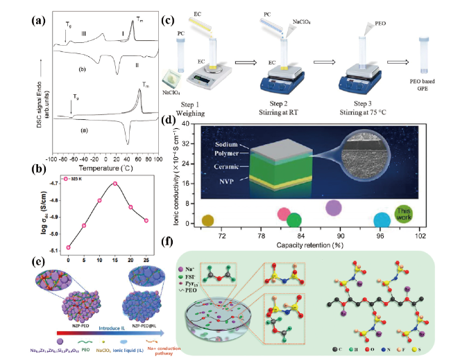
图5 (a)PEO/NaPO3和PEO/NaPO3 + 50%(质量分数)PEG SPE的DSC曲线[58];(b)PEO-PAM共混电解质体系中添加(EC + PC)混合增塑剂的离子电导率[64];(c)PEO/NaClO4/EC-PC SPE的合成示意图[65];(d)具有紧密界面接触的双层PEO-SN-NaClO4|NZSP-NSO电解质[66];(e)NZP-PEO和NZP-PEO@IL CPEs的Na+传导途径示意图[69];(f)PEO/NaClO4-Pyr13FSI SPE组成结构及FSI-阴离子与PEO链相互作用的示意图[70]Fig.5 (a) DSC traces of PEO/NaPO3 and PEO/NaPO3 + 50% PEG SPE[58] ; (b) Ionic conductivity of (EC + PC) mixed plasticizer in PEO-PAM blended electrolyte system[64]; (c) Schematic representation of synthesis route for PEO/NaClO4/EC-PC SPE[65]; (d) The asymmetric PEO-SN-NaClO4|NZSP-NSO SPE with close interface contact[66]; (e) Schematic illustration of the proposed Na+ conduction pathways for the NZP-PEO and NZP-PEO@IL CPEs[69]; (f) Composition of PEO/NaClO4-Pyr13FSI SPE and schematic diagram illustrating the interaction of FSI- anion and PEO chain[70] |
4.3 复合聚合物电解质
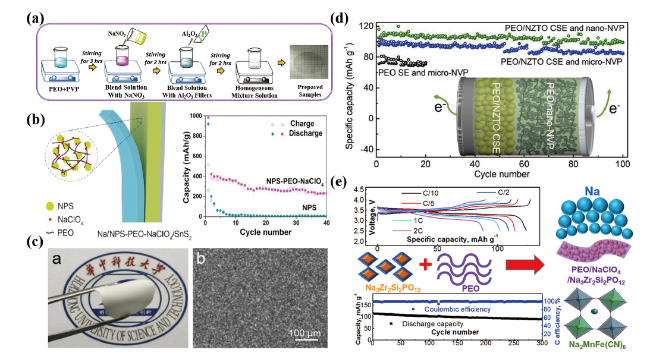
图6 (a)溶液浇铸法制备PEO/PVP/NaPO3/Al2O3 CPE示意图[74];(b)Na3PS4-PEO CPE结构示意图及其在全固态电池中的电化学性能[86];(c)PEO-NZTO CPE的数码照片和背散射电子图像[87];(d)Na|PEO-NZTO|NVP全固态电池在80℃,0.2 C倍率下恒流充放电循环过程中的比容量[87];(e)PEO-NaClO4-NASICON CPE组成示意图及其在全固态电池中的电化学性能[88]Fig.6 (a) Schematic diagram of preparation of PEO/PVP/NaPO3/Al2O3 CPE by solution casting technique[74]; (b) Structure diagram of Na3PS4-PEO CPE and its electrochemical performance in all solid-state batteries[86]; (c) Photograph and back scattered electron image of the PEO/NZTO CPE[87]; (d) Specific capacities of Na|PEO-NZTO|NVP all-solid-state batteries during the galvanostatic charge/discharge cycling at a rate of 0.2 C at 80℃[87]; (e) Schematic diagram of composition of PEO-NaClO4-NASICON CPE and its electrochemical performance in all solid-state batteries[88] |
表4 基于复合聚合物固体电解质离子电导率对比Table 4 Comparison of ionic conductivity based on composite polymer solid electrolyte |
| Electrolyte | Test temperature/℃ | Conductivity/ S·cm-1 | Electrode | Ref |
|---|---|---|---|---|
| PEO/PVP/NaPO3/Al2O3 | RT | > 10-5 | — | 74 |
| PEO/NaClO4/SiO2 | RT | 7.6×10⁻⁶ | — | 75 |
| PEO/NaPF6/NaAl5O8 | 70 | 3.6×10⁻⁶ | Na‖Na | 84 |
| PEO/NaPF6/TiO2 | 80 | 2×10⁻⁴ | Na‖Na3Ti2(PO4)3 | 85 |
| PEO/NaClO4/Na3PS4 | RT | 9.5×10⁻⁴ | Na‖SnS2 | 86 |
| PEO/NaTFSI/NZTO | 80 | 1×10⁻³ | Na‖Na3V2(PO4)3 | 87 |
| PEO/NaClO4/NASICON | 60 | 5.6×10⁻⁴ | Na‖Na2MnFe(CN)6 | 88 |