


1 引言
表1 水系锌离子电池与非水系锂/钠/钾离子电池的对比[4]Table 1 Aqueous zinc-ion battery vs. non-aqueous lithium/sodium/potassium-ion batteries[4] |
| Li | Na | K | Zn | |
|---|---|---|---|---|
| Ionic radius [Å] | 0.76 | 1.02 | 1.38 | 0.75 |
| Cost (USD kg-1) | 19.2 | 3.1 | 13.1 | 2.2 |
| Volumetric Capacity (mAh· cm-3) | 2061 | 1129 | 610 | 5855 |
| Ionic conductivity (S·cm-1) | 10-3~10-2(organic electrolytes) | 10-1~6 (aqueous electrolytes) | ||
| Safety | Low | High | ||
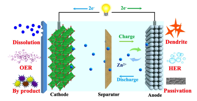
2 正极材料的溶解问题
2.1 锰基材料
2.1.1 电解质中的锰离子添加策略
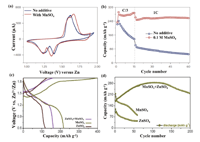
图2 MnO2电极在2 mol/L ZnSO4水电解质中添加和不添加0.1 mol/L MnSO4添加剂的(a)CV曲线和(b)分别在C/3和1 C下的循环性能图[24]。(c)多孔ZnMn2O4正极材料第一圈之后在三种不同电解质中的充放电曲线及(d)相应的循环性能[25]Fig. 2 (a) CV curves and (b) cycling performance at C/3 and 1 C for MnO2 electrode in 2 mol/L ZnSO4 aqueous electrolyte with and without 0.1 mol/L MnSO4 additive[24]. Copyright 2016, Springer Nature (c) Charge and discharge curves of porous ZnMn2O4 cathode material in three different electrolytes after the first cycle and (d) corresponding cycling performance[25]. Copyright 2020, Elsevier |
2.1.2 正极保护层策略
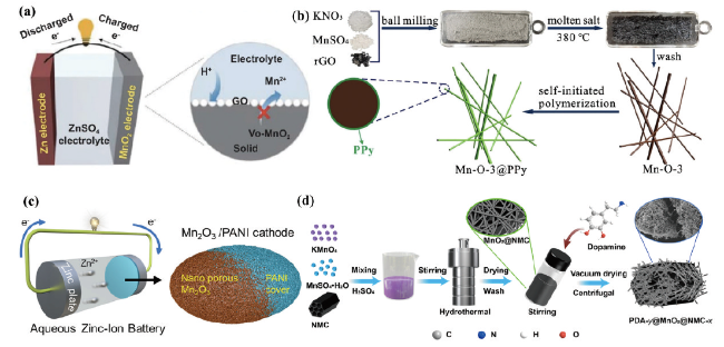
图3 (a)具有氧空位β-MnO2@Graphene氧化物正极材料示意图[27]。(b)MnO2/Mn2O3@PPy复合材料在水系锌离子电池中的应用[28]。(c)超薄聚苯胺涂层的单晶纳米椭圆体电极材料[29]。(d)针状微纳PDA@MnO2@NMC复合材料[30]Fig. 3 (a) Schematic diagram of β-MnO2@Graphene oxide cathode material with oxygen vacancies[27]. Copyright 2021, Springer (b) MnO2/Mn2O3@PPy composite in aqueous Zn-ion battery[28].Copyright 2021, Elsevier. (c) Ultrathin polyaniline coated single crystal nano-ellipsoid electrode materials[29]. Copyright 2022, American Chemical Society (d) Needle-like micro/nano PDA@MnO2@NMC composites[30]. Copyright 2022, American Chemical Society |
2.1.3 电解质界面的人工构建策略

图4 (a)α-MnO2和CMO的反应机理[31]。(b)CEI/H2O界面相互作用能的理论计算,充放电曲线及循环稳定性[13]。(c)利用黏合剂原位生长CEI示意图[32]Fig. 4 (a) Reaction mechanism of α-MnO2 and CMO[31]. (Copyright 2017 American Chemical Society) (b) Theoretical calculation of CEI/H2O interface interaction energy, charge/discharge curves and cycling stability[13]. (Copyright 2022, American Chemical Society) (c) Schematic diagram of in situ growth of CEI using adhesives[32]. Copyright 2021, Wiley |
2.1.4 缺陷工程策略
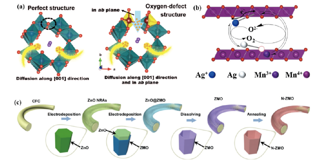
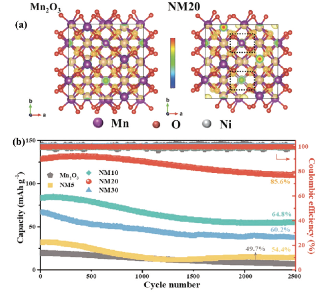
图5 (a)H+扩散到具有完美结构和氧缺陷结构的KMO中的示意图[36]。(b)氧空位缺陷产生示意图[37]。(c)氧空位缺陷ZMO纳米管阵列合成示意图[38]Fig. 5 (a) Schematic representation of H+ diffusion into KMO with perfect structure and oxygen defect structure[36] (Copyright 2019, Wiley). (b) Schematic diagram of oxygen vacancy defect generation[37] (Copyright 2022, American Chemical Society). (c) Schematic diagram of the synthesis of oxygen vacancy-defective ZMO nanotube arrays[38]. Copyright 2021, Elsevier |
2.2 钒基材料
2.2.1 阳离子预插层策略

图7 (a)NVO电极分别在1 mol/L ZnSO4和1 mol/L ZnSO4+1 mol/L Na2SO4电解质中的循环性能图,(b)NVO电极在ZnSO4电解液中的循环性能。插图是不同时间下1 mol/L ZnSO4和1 mol/L ZnSO4+1 mol/L Na2SO4电解质中NVO电极的变化图像,(c)Na2SO4添加剂抑制NVO纳米带的溶解和锌枝晶的形成的示意图[48]Fig. 7 (a) Plots of cycling performance of NVO electrode in 1 mol/L ZnSO4 and 1 mol/L ZnSO4 + 1 mol/L Na2SO4 electrolyte, respectively, (b) cycling performance of NVO electrode in ZnSO4 electrolyte. Insets are images of the changes of NVO electrodes in 1 mol/L ZnSO4 and 1 mol/L ZnSO4 + 1 mol/L Na2SO4 electrolytes at different times, (c) schematic diagram of the inhibition of dissolution of NVO nanoribbons and formation of zinc dendrites by Na2SO4 additives[48]. Copyright 2018, Springer Nature |

图8 BVO-1、BVO-2、BVO-3分别(a)在完全放电状态下的FTIR光谱,(b)在2 mol/L ZnSO4电解质中不同时间的光学图像[50]。不同比例浓度插入阳离子的NZVO正极的电化学性能图:(c)0.1 mV·s-1扫速下的CV曲线图,(d)不同倍率下速率性能,(e)在0.1 A·g-1电流速率下,NZVO-4在400圈后容量保留率为99.6%[51]Fig. 8 (a) FTIR spectra of BVO-1, BVO-2 and BVO-3 in the fully discharged state, (b) optical images at different times in 2 mol/L ZnSO4 electrolyte[50]. Copyright 2020, American Chemical Society. Electrochemical performance of NZVO cathodes with different proportional concentrations of inserted cations. (c) CV plot at 0.1 mV·s-1 sweep rate, (d) rate performance, (e) 99.6% capacity retention of NZVO-4 after 400 cycles at 0.1 A·g-1 current rate[51]. Copyright 2022, American Institute of Physics |
2.2.2 电解质优化策略
2.2.3 固体电解质界面构建策略

图9 (a)原始ZVO正极和通过原子层沉积涂覆HfO2的ZVO的制造过程的示意图,(b)HfO2涂层在ZVO上的高角环形暗场扫描透射图[53]。(c)原位CEI层策略设计的示意图[54]。(d)制备V2O5@PEDOT/CC 的示意图[55]Fig. 9 (a) Schematic of the fabrication process of pristine ZVO cathode and ZVO coated with HfO2 by atomic layer deposition, (b) high angle annular dark field scanning transmission electron microscopy of HfO2 coating on ZVO[53]. Copyright 2019, American Chemical Society (c) Schematic of in situ CEI layer strategy design[54]. Copyright 2021, Wiley (d) Schematic of the preparation of V2O5@PEDOT/CC[55]. Copyright 2019, Wiley |
2.3 总结
3 离子间的静电相互作用

图10 (a)MVO和VO电极在0.1 A·g-1电流下的循环性能图,(b)不同电流密度下的MVO和VO电极的倍率性能图,(c)溶解Zn2+的嵌入/脱出机理示意图[63]。(d)NaV3O8晶体结构,(e)β-Na0.33V2O5晶体结构[66]Fig. 10 (a) Cycling performance plots of MVO and VO electrodes at 0.1 A·g-1 current, (b) multiplicative performance plots of MVO and VO electrodes at different current densities, (c) schematic representation of the embedding/deembedding mechanism of dissolved Zn2+[63]. Copyright 2020, Wiley (d) NaV3O8 crystal structure, (e) β-Na0.33V2O5 crystal structure[66]. Copyright 2019, Wiley |

4 析氧/析氢反应
4.1 析氧反应
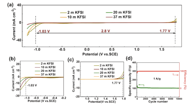
图13 基于KFSI电解液的物理化学性能比较。(a)不同KFSI电解液浓度下的电化学稳定窗口。正极(b)和负极(c)附近区域的放大图。(d)电池在2.3 V电压及1 A/g电流密度时的容量保持率和库仑效率[86]Fig. 13 Comparison of physicochemical properties of KFSI-based electrolytes. (a) ESWs of KFSI electrolyte with different concentrations. Magnified view of the regions outlined near (b) cathodic scan and (c) anodic scan. (d) Capacitance retention and Coulombic efficiency at an operation voltage of 2.3 V at a current density of 1 A/g[86]. Copyright 2021, Elsevier |
4.2 析氢反应
5 锌负极面临的副反应问题
5.1 腐蚀、钝化以及锌枝晶
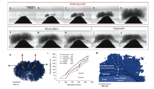
图14 使用多孔隔膜对锌枝晶生长、溶解和再生长的研究(A)200 s、(B)300 s、(C)430 s、(D)590 s和(E)890 s时锌枝晶的生长,(F)120 s、(G)240 s、(H)680 s时的锌枝晶溶解,(I)304 s和(J)656 s时的锌枝晶再生[106]Fig. 14 Study of zinc dendrite growth, dissolution and regrowth using porous separator. Zinc dendrite growth at (A) 200 s, (B) 300 s, (C) 430 s, (D) 590 s and (E) 890 s, (F) 120 s, (G) 240 s, (H) 680 s for each time of zinc dendrite dissolution, (I) 304 s and (J) 656 s for each time of zinc dendrite regrowth[106]. Copyright 2019, Cell Press |
5.2 负极改性
5.2.1 表面改性

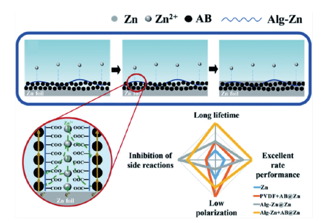
图15 (a)裸锌负极和纳米CaCO3涂层负极的形貌演化图[113]。(b)超薄氮(N)掺杂氧化石墨烯(NGO)层的复合锌金属负极示意图[114]Fig. 15 (a) Morphological evolution of bare zinc anode and nano-CaCO3 coated anode[113]. Copyright 2018, Wiley-VCH Verlag GmbH & Co. KGaA, Weinheim (b) Schematic diagram of a composite zinc-metal anode with an ultrathin nitrogen (N)-doped graphene oxide (NGO) layer[114]. Copyright 2021, Wiley-VCH GmbH |

图16 (a)MX-TMA@Zn的制备示意图。(b)锌离子与不同基底的结合能理论计算结果。(c)电解液和MX-TMA@Zn以及裸锌之间的接触角。(d)裸锌和MX-TMA@Zn的循环性能图[115]Fig. 16 (a) Schematic diagram of the preparation of MX-TMA@Zn. (b) Theoretical calculation of binding energy of Zn ions with different substrates. (c) Contact angle between electrolyte and MX-TMA@Zn and bare zinc. (d) Cycle performance diagram of bare zinc and MX-TMA@Zn[115]. Copyright 2022, Elsevier |

图17 裸锌以及NFZP@Zn复合层(a、c)初始和(b、f)50圈后的SEM图,(c、g)XRD,(d、h)EIS,(i)裸锌和NFZP@Zn复合层的镀锌行为示意图[118]Fig. 17 SEM images of bare zinc as well as NFZP@Zn composite layer (a, c) initially and (b, f) after 50 turns, (c, g) XRD, (d, h) EIS, (i) Schematic diagram of galvanic behavior of bare zinc and NFZP@Zn composite layer[118]. Copyright 2022, Elsevier |
5.2.2 结构优化
5.2.3 电解质优化

图18 (a)TA-SA水凝胶电解质工作示意图。TA-SA水凝胶电解质的SEM表面图(b)、截面图(c),Zn/NH4V4O10电池在(d)2 A·g-1,(e)0.5 A·g-1及零度时的循环性能[129]Fig. 18 (a) Schematic diagram of the operation of TA-SA hydrogel electrolyte. SEM surface view (b), cross-sectional view (c) of TA-SA hydrogel electrolyte, cycling performance of Zn/NH4V4O10 cell at (d) 2 A·g-1, and (e) 0.5 A·g-1 under 0 ℃[129]. Copyright 2022, Elsevier |

图19 (a)制备AIO三维电极系统的操作步骤,(b)AIO电极的横断面照片,(c)扫描电镜图像,(d)利用AIO三维电极系统制作的扣电[133]Fig. 19 (a) Operating steps for preparing the AIO 3D electrode system, (b) cross-sectional photograph of the AIO electrode, (c) scanning electron microscope image, (d) buckling electrode fabricated using the AIO 3D electrode system[133]. Copyright 2021, Oxford Univ Press |