


1 引言
2 富锂锰基层状正极材料的结构特性及电化学行为
2.1 富锂锰基层状正极材料及其结构特征

图1 (a) LiTMO2,(b) Li2MnO3,(c)Li1+xNiaCobMncO2的XRD图谱和晶体结构示意图[26,27,28,29,30];(d)Li[Li0.2Ni0.2Mn0.6]O2的STEM图[31]Fig.1 Crystal structures and XRD of the (a) LiTMO2, (b) Li2MnO3-like, (c) LLi1+xNiaCobMnc[26,27,28,29,30]; (d) Aberration-corrected scanning transmission electron microscopy (STEM) image of the Li[Li0.2Ni0.2Mn0.6]O2 crystal[31] |
2.2 富锂锰基层状正极材料的充放电反应
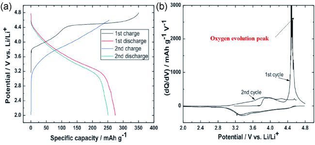
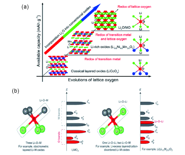
图3 (a)在电化学反应过程中不同层状氧化物的晶格氧参与程度[42];(b)锂过量正极的局域原子配位和电子带结构示意图[50]Fig.3 (a) The participation degree of different layered oxides in lattice oxygen during the electrochemical reaction process[42]. (b) Schematic of local atomic coordination and electron band structure of Li-excess cathodes, that enables the anionic redox reaction[50] |
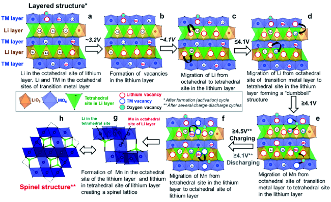
2.3 富锂锰基层状正极材料的结构演变及衰减机理
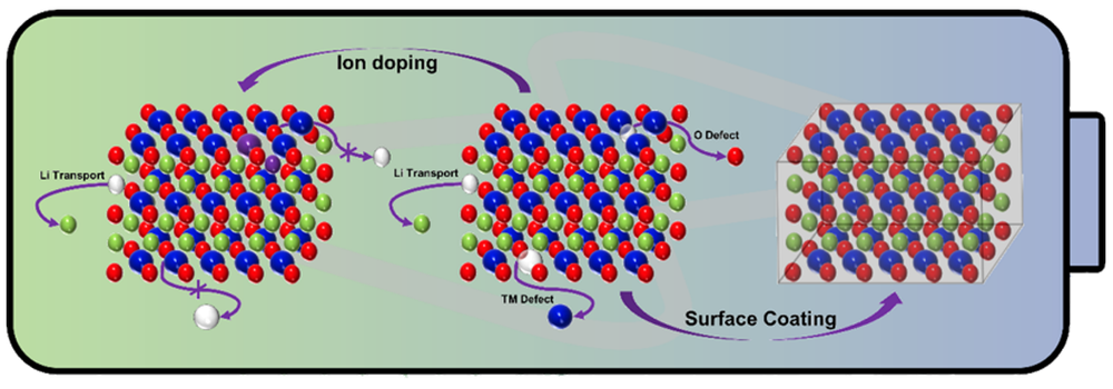
3 掺杂提升富锂锰基层状正极材料的循环稳定性
3.1 锂(Li)位掺杂
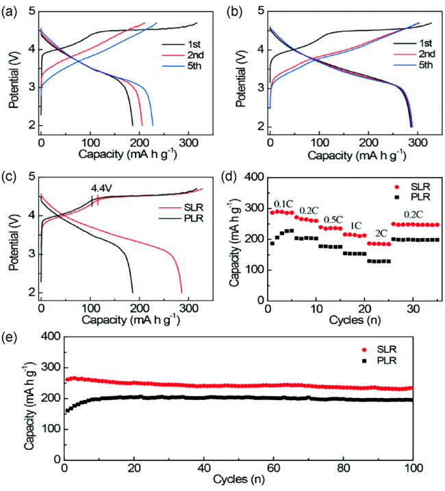
图5 (a,b)在0.1 C下,未改性的正极材料(PLR)和改性后的正极材料(SLR)的充放电曲线;(c,e)在0.2 C下,PLR和SLR的充放电曲线和循环性能图;(d)PLR和SLR的倍率性能图[68]Fig.5 (a, b) The charge-discharge curves of the unmodified anode material (PLR) and modified anode material (SLR) at 0.1 C, respectively. (c, e) the charge-discharge curves and cycling stability tested at 0.2 C and (d) rate performance of PLR and SLR[68] |
3.2 过渡金属(TM)位掺杂
3.3 氧(O)位掺杂
4 表面修饰提升富锂锰基层状正极材料循环稳定性
4.1 表面包覆
4.2 表面处理
5 联合改性机制
表1 近年来关于富锂锰基正极材料改性策略的代表性研究工作及其相关材料的主要电化学性能Table 1 Electrochemical performance of typical modification research works about lithium-rich manganese-based layered cathode materials in recent years |
| Molecular formula | Classification | Electrochemical property | ref | |
|---|---|---|---|---|
| Capacity retention | Rate capacity (mAh·g-1) | |||
| Li1.2Mn0.54Ni0.13Co0.13O2 | Li site doping | 76%→95% (100 cycles) | 180→210 at 500 mA·g-1 | 67 |
| Li1.2Mn0.54Ni0.13Co0.13O2 | Li site doping | 65%→71% (300 cycles) | 81→136 at 1500 mA·g-1 | 69 |
| Li1.5Mn0.675Ni0.1675Co0.1675O2 | TM site doping | 78%→ 82% (150 cycles) | 65→120 at 5000 mA·g-1 | 70 |
| Li1.133Mn0.467Ni0.2Co0.2O2 | O site doping | 83%→97% (50 cycles) | 212→236 at 25 mA·g-1 | 72 |
| SQ〗0.33Li2MnO3·0.67Li [Mn1/3Ni1/3Co1/3]O2 | C-coating | 50%→69% (50 cycles) | 75→234 at 2500 mA·g-1 | 79 |
| Li1.256Ni0.198Co0.082Mn0.689O2.25 | Al2O3-coating | 82%→95% (60 cycles) | 123→189 at 250 mA·g-1 | 81 |
| Li1.3Mn4/6Ni1/6Co1/6O2.4 | AlF3-coating | 81%→91% (50 cycles) | 53→80 at 1250 mA·g-1 | 82 |
| Li1.15Ni0.7Co0.11Mn0.57O2 | AlPO4-coating | 85%→90% (100 cycles) | 198→202 at 250 mA·g-1 | 85 |
| SQ〗0.35Li2MnO3·0.65Li Ni0.35Mn0.45Co0.20O2 | NH3 heat treatment | 89%→ 94% (60 cycles) | 163→183 at 1000 mA·g-1 | 90 |
| Li1.2Mn0.54Ni0.13Co0.13O2 | C-coating & F-doping | 57%→ 89% (500 cycles) | 33.3→108.6 at 2500 mA·g-1 | 92 |
| Li1.20Mn0.54Ni0.13Co0.13O2 | ZrF4-coating & Mo-Doping | 87%→92% (100 cycles) | 95.2→117.1 at 1250 mA·g-1 | 93 |