


1 引言
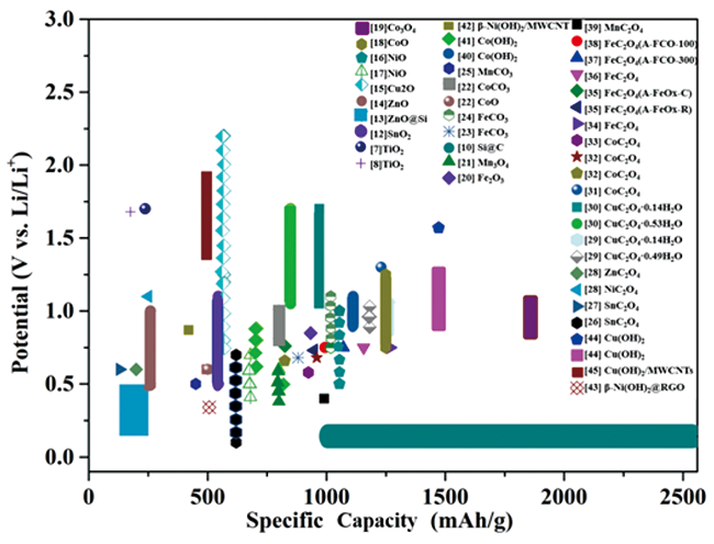
图1 过渡金属基电极材料放电比容量与嵌锂电位图(过渡金属草酸盐[26⇓⇓⇓⇓⇓⇓⇓⇓⇓⇓⇓⇓~39]、过渡金属含氧酸盐[22⇓⇓~25,40⇓⇓⇓⇓~45]、氧化物[11⇓⇓⇓⇓⇓⇓⇓⇓⇓⇓~22]和其他类型的负极材料[7,8,10])Fig. 1 Lithiation potential (cathodic peak) vs. specific capacity for various transition metal-based electrode materials (transition metal oxalates[26⇓⇓⇓⇓⇓⇓⇓⇓⇓⇓⇓⇓~39], transition metal oxysalt[22⇓⇓~25,40⇓⇓⇓⇓~45], oxides[11⇓⇓⇓⇓⇓⇓⇓⇓⇓⇓~22],other types of negative electrodes[7,8,10]) |
2 草酸盐材料的晶体结构特征
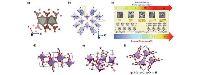
图2 不同金属草酸盐晶体结构示意图: a) CoC2O4[53]; b) FeC2O4·2H2O[37]; c) FeC2O4·2H2O晶型演变机理图[57]; d) α-MnC2O4·2H2O, e) γ-MnC2O4·2H2O, f) MnC2O4·3H2O[54]Fig. 2 Diagram of crystal structure of different metal oxalates: a) CoC2 O4[53].Copyright 2018, American Chemical Society; b) FeC2O4·2H2O[37].Copyright 2020, Elsevier; c) FeC2O4·2H2O crystal evolution mechanism diagram[57].Copyright 2020, Elsevier; d) α-MnC2O4·2H2O, e) γ-MnC2O4·2H2O, f) MnC2O4·3H2O[54]. Copyright 2020, American Chemical Society. |
3 在锂离子电池方面的应用
3.1 金属草酸基材料传统储锂机制
3.1.1 含结晶水金属草酸盐材料
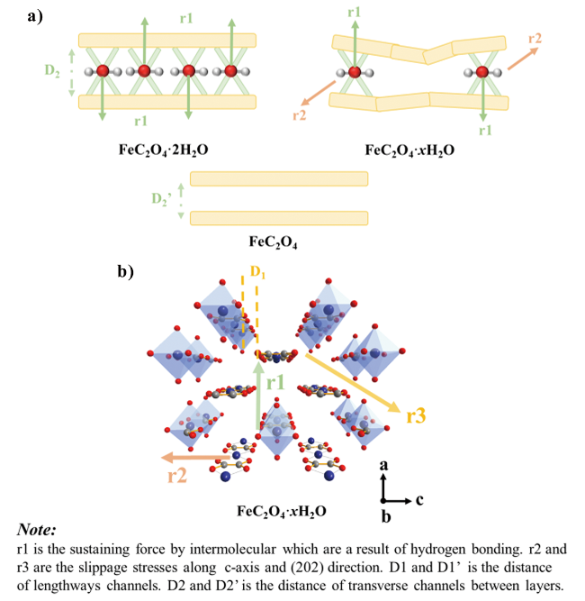
图3 不同温度下FeC2O4·xH2O (x∈[0,2])层状结构演变示意图: a) 材料结构内部应力分布与结晶水含量变化关系示意图: b) 材料内部锂离子扩散通道和应力分布[37]Fig. 3 Schematic of the evolution in layered structure sintered at different temperatures: a) The stress distribution vs. Crystal water content; b) Diagram of lithium ion diffusion channel and stress distribution[37]. Copyright 2020, Elsevier |
3.1.2 不带结晶水金属草酸盐材料
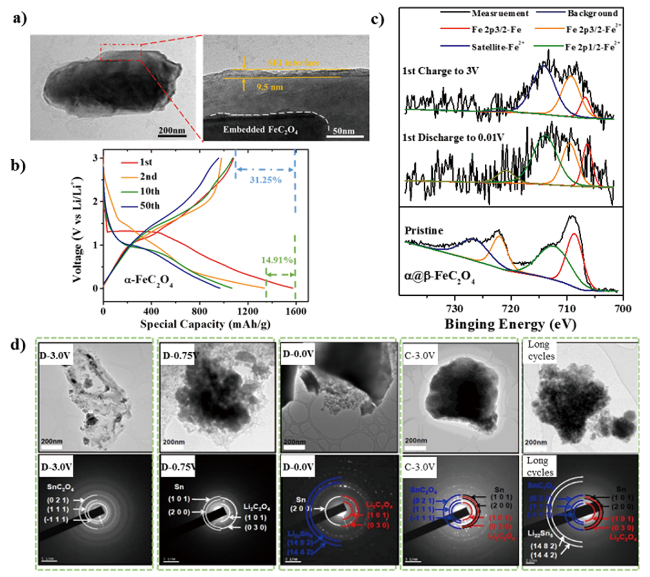
图5 a) α@β-FeC2O4电极在0.5 C倍率下循环100圈后的TEM图; b) α@β-FeC2O4材料恒流充放电曲线; c) 首次循环后电极反应产物的XPS图谱[36]; d) SnC2O4/rGO复合电极材料在放、充电及长循环的TEM图[26]Fig. 5 a) TEM image of α@β-FeC2O4 electrode material after 100 cycles at 0.5 C rate; b) Galvanostatic discharge/charge curves of the different cycles for α@β-FeC2O4 electrodes at 0.1 C (0.1 A/g); c) XPS spectra of Fe 2p for α@β-FeC2O4 electrodes upon lithiation and delithiation during the first cycle[37]. Copyright 2020, Elsevier; d) TEM image of SnC2O4 /rGO electrode during discharge, charge and after extensive cycles[26].Copyright 2017,American Chemical Society |
3.2 金属草酸盐新型储锂机制
3.2.1 额外容量的可能来源
3.2.2 容量增长现象的产生
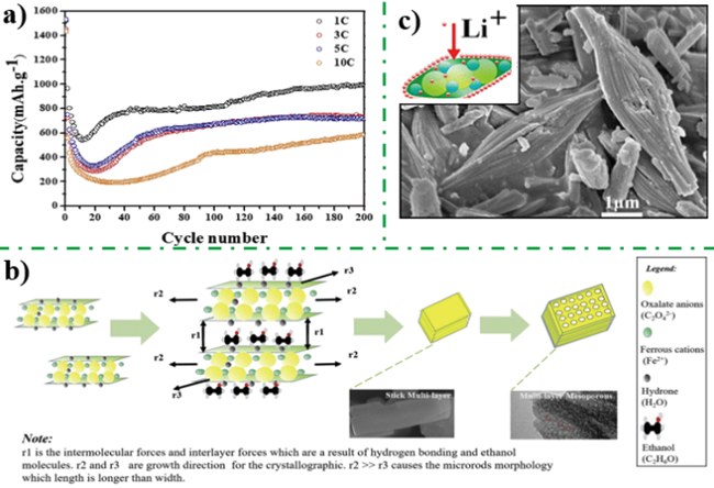
图6 a) 层状草酸亚铁电极材料循环性能, b)多层介孔结构草酸亚铁形成机理图[38]; c)茧状草酸亚铁电极材料反应活性位点图[35]Fig. 6 a) Cycle performance curve of multilayer iron oxalate with mesoporous nanostructure,b) Schematic illustration for synthesis of multilayer iron oxalate with mesoporous nanostructure[38].Copyright 2018, Elsevier; c) Diagram for active site of cocoon iron oxalate[35]. Copyright 2012, American Chemical Society |
3.3 金属草酸基材料储锂动力学
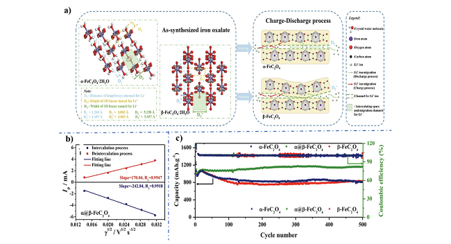
图7 a) α, β-FeC2O4晶体结构内部锂离子传输路径示意图; b) α@β-FeC2O4电极脱/嵌过程中阳极峰电流(Ip)与循环伏安扫描速率平方根(γ1/2)线性关系图; c) α-FeC2O4、β-FeC2O4、α@β-FeC2O4三种材料长循环性能曲线[36]Fig. 7 a) Mobility mechanism for Li+ ions in different polymorphs; b) Linear relation of the anodic peak current (Ip) and the square root of the scan rate (γ1/2) for intercalation and deintercalation process; c) Long-term cycling performance and coulombic efficiency at constant of 0.5 A/g[36]. Copyright 2019, Elsevier. |
3.4 金属草酸基材料改性策略
3.4.1 材料形貌晶型控制
表1 不同形貌金属草酸基材料性能对比表Table 1 Electrochemistry property of various metal oxalates with different morphologies (1 C = 1 Li h-1·mol-1) |
| Metal oxalates | Theoretical capacity (mAh /g) | Coulombic efficiency (1st) | Long-term cycle behavior (capacity, cycle, current (A/g)) | Capacity retention | ref |
|---|---|---|---|---|---|
| MnC2O4 nanoribbon | 374.95 | 47.62% | 250 (100th, 1 C) | 23.81% | 28 |
| MnC2O4 microtubes | 374.95 | 48.10% | 990 (100th, 0.375) | 76.94% | 39 |
| FeC2O4 multilayer and mesoporous | 372.58 | 63.29% | 993.3 (200th, 1 C) | 65.30% | 38 |
| FeC2O4·2H2O(A-FCO-55) | 297.95 | 47.92% | 550 (300th, 0.5) | 36.26% | 37 |
| FeC2O4(A-FCO-300) | 372.58 | 72.22% | 1040 (300th, 0.5) | 72.22% | 37 |
| α@β-FeC2O4 | 372.58 | 79.86% | 1156.27 (500th, 0.5) | 72.69% | 36 |
| FeC2O4 concoons | 372.58 | - | 825 (100th, 1 C) | 63.95% | 35 |
| FeC2O4 rods | 372.58 | - | 906 (100th, 1 C) | 69.16% | 35 |
| FeC2O4·2H2O microrods | 372.58 | - | 346 (100th, 0.5 C) | 25.82% | 70 |
| FeC2O4 array | 372.58 | - | 1267 (200th, 0.756) | 34 | |
| CoC2O4 nanorods | 364.77 | 61.96% | 924 (100th, 0.05) | 57.43% | 33 |
| CoC2O4 nanorods | 364.77 | 62.16% | 959 (100th, 1 C) | 59.97% | 32 |
| CoC2O4 nanosheets | 364.77 | 64.89% | 741 (100th, 1 C) | 48.81% | 32 |
| Porous CoC2O4 nanorods | 364.77 | - | 1230 (100th, 0.5) | 80.60% | 31 |
| NiC2O4·2H2O nanorods | 293.32 | 67.70% | 578.9 (100th, 0.5) | 54% | 59 |
| NiC2O4 nanorods | 365.36 | 59.20% | 300 (100th, 0.5) | 42.86% | 59 |
| NiC2O4 nanoribbon | 365.36 | 67.00% | 250 (60th, 2 C) | 22.73% | 28 |
| CuC2O4·0.14H2O cylinder | 43.10% | 970 (100th, 0.2) | 105.40% | 30 | |
| CuC2O4·0.53H2O rod | 42.00% | 849.3 (100th, 0.2) | 70.11% | 30 | |
| CuC2O4·0.14H2O spherical | 57% | 1260.4 (100th, 0.2) | 87.77% | 29 | |
| CuC2O4·0.49H2O cotton | 37.60% | 1181.1 (100th, 0.2) | 69.93% | 29 | |
| CuC2O4·xH2O caky | 51.20% | 873 (100th, 0.1) | 106.59% | 71 | |
| ZnC2O4 nanoribbon | - | 200 (75th, 2 C) | 18.52% | 28 | |
| SnC2O4 | 46.00% | 170 (200th, 0.1) | 12.20% | 26 |
3.4.2 颗粒界面碳复合改性
3.4.3 金属元素掺杂
4 在其他离子电池方面的应用
4.1 钠离子电池
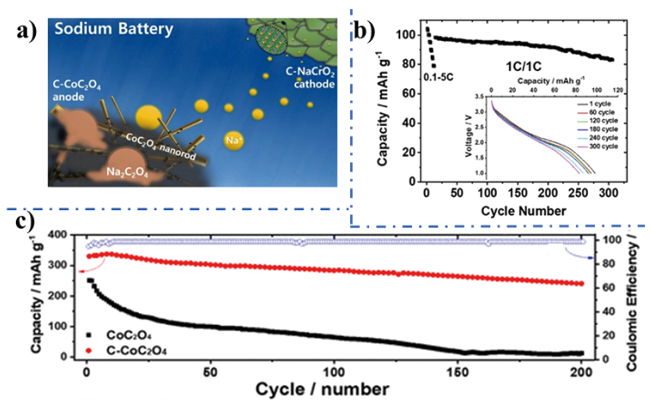
图8 a) C-NaCrO2//C-CoC2O4全电池示意图; b) C-NaCrO2//C-CoC2O4全电池在(0.1~5 C)电流倍率下的放电曲线(插图: 不同循环次数对应的放电曲线); c) C-CoC2O4电极循环稳定性测试曲线[53]。Fig. 8 a) Schematic illustration of the C-NaCrO2//C-CoC2O4 full cell; b) Discharge profile vs cycle number at different current rates (0.1~5 C) of the C-NaCrO2//C-CoC2O4 full cell (inset: discharge curves vs cycle number); c) C-CoC2O4 electrode cyclability (blue line: Coulombic efficiency of C-CoC2O4)[53]. Copyright 2018, American Chemical Society. |
4.2 钾离子电池
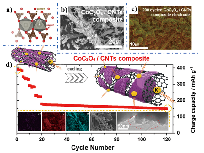
图9 a) CoC2O4结构模型; b) CoC2O4/CNTs复合材料扫描电镜图; c ) CoC2O4/CNTs复合电极循环200圈后SEM图; d) CoC2O4/CNTs复合电极材料循环示意图[87]Fig. 9 a) CoC2O4 structural model; b) SEM image of CoC2O4/CNTs composite; c) SEM image of CoC2O4/CNTs composite electrode after 200 cycle; d) Schematic illustration for the degradation of CoC2O4/CNTs composite[86]. Copyright 2020, American Chemical Society. |