


1 引言
2 聚合物固体电解质
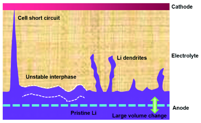
3 聚合物电解质/锂负极界面挑战
4 聚合物电解质/锂负极界面改性策略
4.1 无机填料
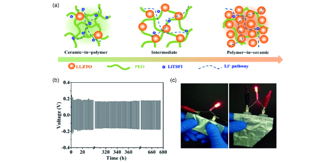
图2 (a)PEO-LLZTO复合固体电解质结构示意图;(b)锂对称电池的恒流充放电曲线(0.5 mA·cm-2,55 ℃);(c)柔性软包电池安全性展示[68]Fig. 2 (a) Schematic illustration for PEO-LLZTO composite electrolyte;(b) galvanostatic cycling curves of the lithium symmetrical cell at a current density of 0.5 mA·cm-2 at 55 ℃;(c) safety illustration of flexible pouch lithium metal cell[68] |
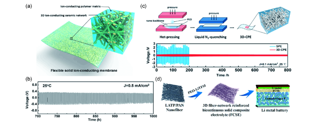
图4 采用无机纳米纤维增强的PEO基复合固体电解质,(a)LLZO纳米纤维膜的结构示意图;(b)采用PEO-LLZO复合电解质的对称锂电池循环性能[71];(c)LLTO纳米纤维增强PEO基复合固体电解质的制备过程和相应对称锂电池的循环性能[74];(d)PAN-LATP纤维及其增强复合电解质在固态锂电池中的应用示意图[76]Fig. 4 PEO based composite solid electrolyte enhanced with inorganic nano fiber,(a) schematic of LLZO nano fiber membrane;(b) cycling performance of symmetrical Li-Li cells with PEO-LLZO electrolyte[71];(c) the preparation process of PEO based composite electrolyte enhanced with LLTO nano fiber membrane, the cycling performance of symmetrical Li-Li cells with PEO-LLTO electrolyte[74];(d) schematic of PAN-LATP nano fiber, the corresponding composite electrolyte and solid-state lithium battery[76] |
4.2 高强度基底膜
4.3 分级层状结构设计
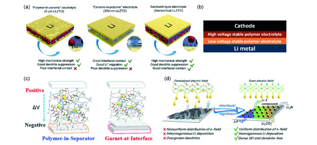
图5 (a)采用5 μm LLZTO、200 nm LLZTO的复合电解质和分级三明治结构复合电解质的结构示意图[85];(b)双层聚合物电解质固态锂电池的层状结构图[55];分级层状复合固体电解质结构(c)及其界面优势(d)示意图[86]Fig. 5 (a) Schematic illustration of the polymer-in-ceramic electrolyte(5 μm LLZTO), ceramic-in-polymer electrolyte(200 nm LLZTO), and hierarchical sandwich-type composite electrolytes[85];(b) Stacking model of double-layer polymer electrolyte in an all-solid-state battery[55];Schematic illustrations for superiorities of(c) modified solid electrolyte and(d) interfacial regulation of hierarchical composite solid electrolyte[86] |
4.4 界面缓冲层

图6 (a)溶液浇铸结合原子层沉积法制备Al2O3涂覆PEO-LiTFSI电解质的制备过程示意图;(b)PEO-LiTFSI和PEO-LiTFSI-Al2O3电解质的高分辨O 1s XPS图谱;(c)采用PEO-LiTFSI-Al2O3电解质组装的对称锂电池在不同电流密度下电压随时间的变化曲线[87]Fig. 6 Schematic illustration of the successive deposition of the PEO-LiTFSI electrolyte(solvent casting) and Al2O3 layer(Atomic layer deposition);(b) high-resolution O 1s XPS spectra of PEO-LiTFSI and PEO-LiTFSI-Al2O3 electrolytes;(c) potential profiles of the symmetric cell using PEO-LiTFSI-Al2O3 at different current densities[87] |
4.5 交联网络结构设计
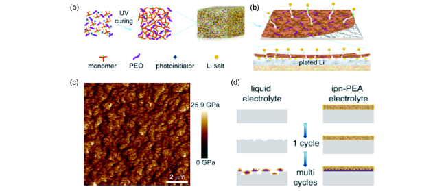
图7 (a)原位聚合双功能聚合物电解质的合成示意图;(b)锂金属在双功能电解质中电化学沉积行为;(c)双功能电解质杨氏模量的原子力显微镜图谱;(d)传统电解液和双功能电解质对应的锂沉积行为[94]Fig. 7 Illustration of the in-situ preparation of the bifunctional cross-linking electrolyte;(b) Proposed electrochemical deposition behavior of Li metal with bifunctional electrolyte;(c) Young’s modulus mapping, and(d) illustration of the proposed Li deposition behavior using liquid and bifunctional electrolyte[94] |
4.6 固态锂负极保护策略

图8 (a)PTFE-LLZTO-SN电解质的制备过程;(b)PTFE-LLZTO-SN电解质膜分别匹配Li和Li-FEC负极的示意图;室温下,采用PTFE-LLZTO-SN电解质膜的Li对称电池和Li-FEC对称电池的(c)阻抗随时间变化和(d)恒流充放电曲线[100]Fig. 8 (a) The preparation schematic of PTFE-LLZTO-SN electrolyte;(b) schematic of the interface on the PTFE-LLZTO-SN electrolytes respect to Li and Li-FEC anode;(c) Electrochemical impedance spectra at different storage time and (d) galvanostatic cycling curves of the symmetric Li and Li-FEC batteries at 25 ℃[100] |
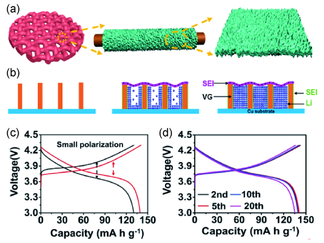
图9 (a)石墨烯/铜网(VGCM)集流体的结构示意图;(b)限域空间中的锂沉积示意图;(c)分别采用锂箔和VGCM@Li组装的固态锂电池循环十次对应的充放电曲线;(d)不同循环次数对应的LiNi0.5Co0.2Mn0.3O2|VGCM@Li固态锂电池的充放电曲线[105]Fig. 9 (a) Schematic illustration of the synthetic procedure of the VGCM;(b) lithium deposition diagram in confined nanospace;(c) galvanostatic discharge/charge profile of solid-state batteries with Li or VGCM@Li anode at 0.5 C(10 cycles);(d) galvanostatic discharge/charge profile of LiNi0.5Co0.2Mn0.3O2|VGCM@Li battery at different cycles[105] |