


1 Introduction
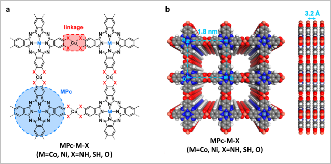
图1 (a)酞菁基MOFs的合成图;(b)酞菁基MOFs在堆叠模式下的一般结构反应的俯视图和侧视图[19]Fig. 1 (a) Synthetic illustration for phthalocyanine-based c-MOFs; (b) top and side view of a general structural representation of phthalocyanine-based c-MOFs in eclipsed stacking mode. Reproduced with permission from Ref 19. Copyright 2021. American Chemical Society |
2 Conductive mechanisms
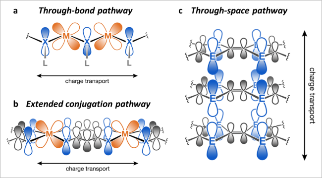
图2 导电机理:(a)贯穿键;(b)扩展偶联及π-d偶联;(c)通过空间及有机部分的π-π堆积[12]Fig. 2 (a) The through-bond pathway. (b) The extended conjugation pathway also involves π-d conjugation. (c) The through-space pathway involves π-π stacking of organic moieties. Reproduced with permission from Ref 12. Copyright 2021. American Chemical Society |
3 Electrocatalysis
3.1 Water electrolysis
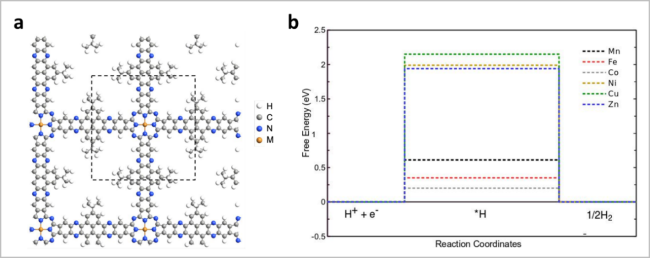
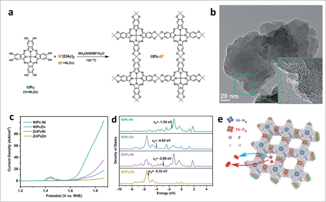
图5 (a)构建MPc-M'-MOF的示意图;(b)NiPc-Ni-MOF的TEM图;(c)MPc-M'-c-MOF的LSV曲线;(d)不同双金属c-MOFs的PDOS谱图;(e)NiPc-Ni c-MOF中Ni-O4和Ni-N4位点的示意图[35]Fig. 5 (a) Strategy for constructing MPc-M’-MOF; (b) TEM image of NiPc-Ni c-MOF; (c) linear sweep voltammetry (LSV) curves of MPc-M’ c-MOF; (d) PDOS of different dual-metal c-MOFs; (e) scheme of Ni-O4 and Ni-N4 sites in NiPc-Ni c-MOF. Reproduced with permission from Ref 35. Copyright 2021. Royal Society of Chemistry |
3.2 Oxygen reduction reaction
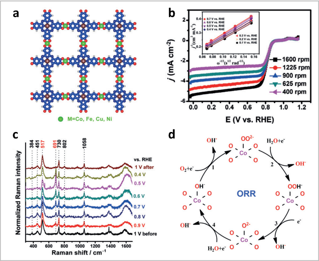
图6 (a)PcCu-O8-M的模拟结构;(b) PcCu-O8-Co/CNT的极化曲线;(c) ORR过程中的原位拉曼分析;(d)ORR反应机理[38]Fig. 6 (a) Simulated structure of PcCu-O8-M (red: O, blue: C, white: H, brown: Cu, green: metal atoms, M = Co, Fe, Ni, Cu). (b) ORR polarization curves of PcCu-O8-Co/CNT. (c) In situ Raman analysis during the ORR process. (d) proposed reaction mechanism. Reproduced with permission from Ref 38. Copyright 2021. Wiley-VCH GmbH |
3.3 CO2 reduction reaction
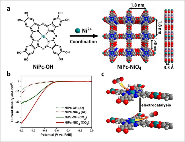
图7 (a)NiPc-NiO4 c-MOF的合成示意图;(b)NiPc基c-MOFs在CO2/Ar饱和0.5 M KHCO3中的LSV曲线;(c)CO2RR示意图[46]Fig. 7 (a) Scheme of NiPc-NiO4 c-MOF nanosheets. Top and side view of their structures with 2 × 2 square grids in AA-stacking mode; (b) LSV curves of NiPc-based c-MOFs in CO2/Ar-saturated 0.5 M KHCO3; (c) Illustration of the CO2RR. Reproduced with permission from Ref 46. Copyright 2021. Wiley-VCH GmbH |
3.4 N2 reduction reaction
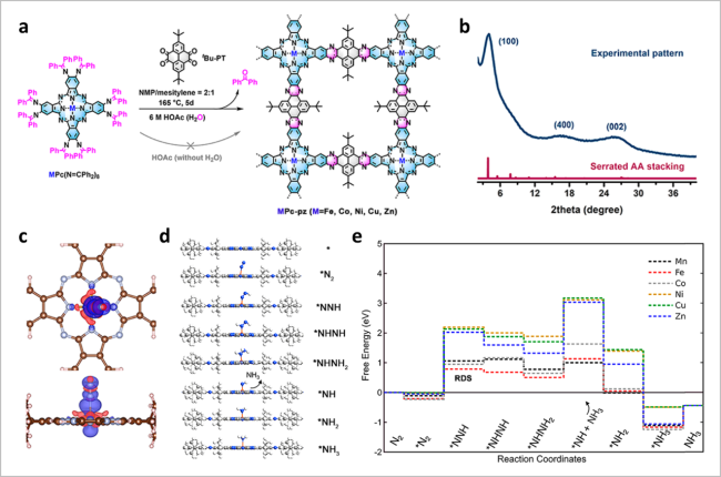
图8 (a)MPc-pz的合成示意图;(b) MPc-pz的XRD图谱;(c)FePc-pz上吸附的N2电荷密度差异图;(d)NRR各种中间体的优化结构;(e)NRR在MPc-pz上沿交替路径的自由能分布[34]Fig. 8 (a) Scheme of MPc-pz; (b) XRD patterns of MPc-pz; (c) charge density differences of N2 adsorbed on FePc-pz; (d) optimized structures of various intermediates for NRR. (e) Free energy profiles of NRR along the alternating pathway on MPc-pz. Reproduced with permission from Ref 34. Copyright 2021. American Chemical Society |