


1 引言
2 固体电解质研究现状及趋势
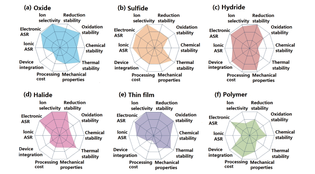
表1 常见无机固体电解质的特性和优缺点[40,41]Table 1 The characteristics, advantages, and disadvantages of common inorganic solid electrolytes[40,41] |
| Type | Selected materials | Conductivity (S·cm-1) | Potential window (V (vs Na+ / Na)) | Advantages | Disadvantages |
|---|---|---|---|---|---|
| Oxides | Na-β″-Al2O3, NASICON, Na2M2TeO6, | 10-4 ~ 10-3 | Up to 7 | High thermal stability High ionic conductivity | High interface resistance Poor interface wetting |
| Sulfides | Na3PS4, Na11Sn2PS12, etc. | 10-4 ~ 10-3 | < 4 for Na3PS4 Others up to 5 | High ionic conductivity High flexibility | Low chemical stability, Poor compatibility with Na |
| Polymer based | PEO, PEG, PVDF-HFP, etc. | 10-6 ~ 10-4 | About 4.5 | High flexibility Good interface wetting | Low ionic conductivity, Low thermal stability High cost |
| Boron hydrides | Na2-x(B12H12)x(B10H10)1-x Na2-x(CB11H12)x(B12H12)1-x, etc. | 10-4 ~ 10-2 | Up to 5 | High thermal stability High chemical stability High ionic conductivity | Large interfacial resistance |
| Gel Polymer | EPTA-NaPF6-PC/FEC/PS-NaPF6, BP/PEO-HKUST-1-NaClO4-EC/ DEC/FEC, etc. | 10-4 ~ 10-3 | Up to 5 | High ionic conductivity High flexibility Good interfacial stability | Low thermal stability High cost |
2.1 无机固体电解质
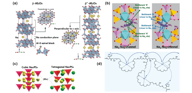
图2 (a)β-Al2O3和β″-Al2O3晶体结构[26];(b)Na3Zr2Si2PO12钠离子传输路径示意图[27];(c)Na3PS4晶体结构[26];(d)聚合物固体电解质Na+传导机理图[54]Fig.2 (a) Crystal structures of β-Al2O3 and β″-Al2O3[26]; (b) schematic illustration of Na+ conducting pathways in Na3Zr2Si2PO12[27]; (c) crystal structures of the Na3PS4[26]; (d) schematic illustration of Na+ transport mechanism in polymer solid electrolytes[54] |
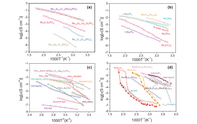
图3 无机固体电解质Na+电导率随温度变化[87]:(a)NASICON;(b)硫化物固体电解质;(c)聚合物和复合固体电解质;(d)结晶态有机物、反钙钛矿和硼氢化物固体电解质Fig.3 Temperature-dependent Na+ conductivities of inorganic solid electrolytes[87]: (a) NASICON; (b) sulfide solid electrolytes; (c) polymer and composite solid electrolytes; (d) crystalline organic, anti-perovskites and borohydrides solid electrolytes |
2.2 聚合物固体电解质
2.3 复合固体电解质
3 全固态钠离子电池挑战
3.1 SSBs界面及机械稳定性
3.2 界面化学和电化学稳定性
3.3 界面空间电荷效应
3.4 枝晶对电池性能影响
4 全固态钠离子电池界面工程
4.1 正极/SEs界面
4.1.1 添加界面润湿剂
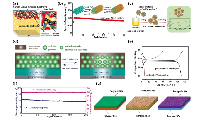
图5 (a)NVP|IL/SE|Na电池界面示意图[58];(b)Na2S-Na3PS4-CMK-3复合正极示意图[95];(c)S-MSP20-Na3SbS4正极制备工艺[96];(d,e)正极活性材料与塑性晶体固体电解质复合正极示意图[97];(f)Na|PEO-SN-NaClO4/PAN-Na3Zr2Si2PO12-NaClO4|PB电池在0.2 C下循环性能图[98];(g)非对称固体电解质示意图Fig.5 (a) Schematic of the interface for NVP|IL/SE|Na batteries[58]; (b) schematic of the Na2S-Na3PS4-CMK-3 composite cathode[95]; (c) preparation process for S-MSP20-Na3SbS4 cathode[96]; (d, e) schematic of plastic-crystal electrolyte and active material in composited cathode[97]; (f) cycling performance of the Na|PEO-SN-NaClO4/PAN-Na3Zr2Si2PO12-NaClO4|PB cell at 0.2 C[98]; and (g) illustration of the asymmetric solid electrolytes |
4.1.2 复合正极材料
4.1.3 复合固体电解质
4.2 负极/SEs界面
4.2.1 表面涂层修饰
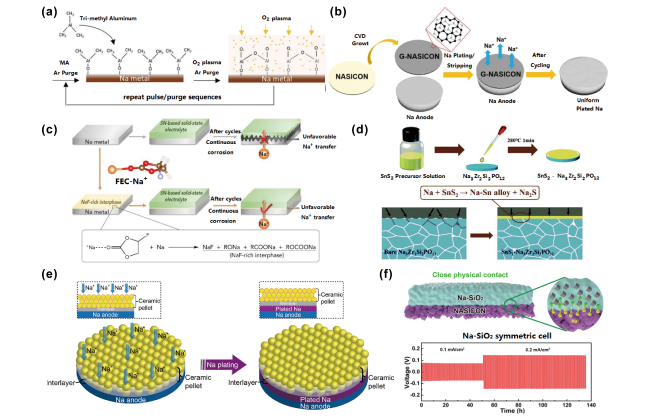
图6 (a)PEALD构筑Al2O3钝化层示意图[105];(b)化学气相沉积石墨烯修饰NASICON表面示意图[106];(c)NaClO4/FEC溶液改性Na金属表面示意图[107];(d)Na|SnS2-Na3Zr2Si2PO12界面改性示意图[108];(e)固体电解质与金属Na界面接触模型[109];(f)Na-SiO2复合材料与NASICON界面[110]Fig.6 (a) Schematic of PEALD process for Al2O3 layer[105]; (b) schematic of the CVD-grown graphene-like interlayer on NASICON surface[106]; (c) NaClO4/FEC modified surface of Na[107]; (d) schematic of the Na|SnS2-Na3Zr2Si2PO12 interface[108]; (e) contact model of SEs and sodium metallic[109]; (f) interfaces between Na-SiO2 composite and NASICON[110] |
4.2.2 固体电解质界面层(SEI)
4.2.3 柔性电解质夹层
4.2.4 复合负极材料
4.3 电池结构设计
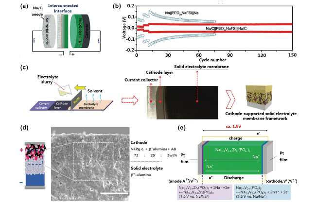
图7 (a)金属钠-碳复合负极与固体聚合物化学交联界面示意图[112];(b)Na-C|PEO20NaFSI| Na-C和Na|PEO20NaFSI|Na电池在0.1、0.2和0.3 mA下循环电压曲线[112];(c)正极和固体电解质叠层薄膜示意图[113];(d)Na2FeP2O7正极与β''-Al2O3电解质一体化结构示意图[114];(e)Pt|Na3-xV2-xZrx(PO4)3|Pt单相全固态电池示意图[115]Fig.7 (a) Illustration of the interfaces between solid-state polymer and Na-C anode[112]; (b) voltage curves of the Na-C|PEO20NaFSI| Na-C and Na|PEO20NaFSI|Na batteries at a current density of 0.1, 0.2, and 0.3 mA[112]; (c) schematic of the cathode-supported solid electrolyte membrane[113]; (d) illustration of the Na2FeP2O7 and β''-Al2O3 integrated structure[114]; (e) schematic illustration of the Pt|Na3-xV2-xZrx(PO4)3|Pt battery[115] |