


Contents
1 引言
2 超浸润光热材料的构筑研究现状
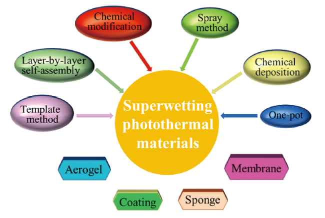
图2 超浸润光热材料的构筑方法Fig. 2 The construction methods of superwetting photothermal materials |
表1 超浸润光热材料的制备方法对比Table 1 The comparison of preparation methods of superwetting photothermal materials |
| Methods | Products | Principle | Advantage | Disadvantage | ref |
|---|---|---|---|---|---|
| Chemical modification | Superhydrophobic CNT@PVP membrane (S-CPM) | Carbon-based photothermal materials modified with low surface energy. | Facile and inexpensive | Abiotic friendliness; Non-environmental friendly | 24 |
| Spray method | Superhydrophobic SiC/ CNTs coatings | SiC/CNTs provide a micro/nano hierarchical structure while FAS-17 for low surface energy modification. | Simple preparation process | Poor abrasion resistance | 25 |
| Layer-by-layer self-assembly method | Superhydrophobic photothermal cotton fabric | The surface of the fiber is roughened by CNTs which give photothermal properties at the same time. | Good chemical stability | Cumbersome preparation process | 26 |
| Template method | Photothermal superhydrophobic surface with regular array structure | Superhydrophobic effect can be achieved by adding regular array microstructure after curing PDMS. | Simple and rapid preparation process | Sophisticated equipment | 27 |
| Chemical Deposition | A superhydrophobic aerogel | Carbon nanotubes were combined by chemical vapor deposition. | Green, efficient and low-cost | Complex process | 28 |
| One-pot | Magnetic superhydrophobic particles | The producs are prepapred via sol-gel reaction. | Facile,Inexpensive,environmental-friendly | Difficult to accurately control | 29 |
2.1 碳基超浸润光热材料
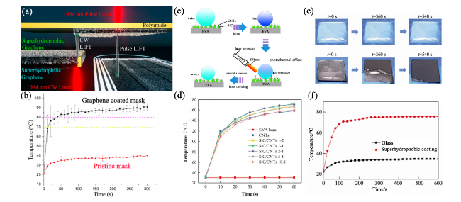
图3 (a) 石墨烯掩膜制备方法; (b) 红外照射下原掩膜与石墨烯掩膜升温情况[30]; (c) SiC/CNTs涂层的光热除冰示意图; (d)红外照射下不同样品温度变化曲线[25]; (e) 玻璃(上)及炭黑超疏水涂层(下)在一个太阳强度下的光热除冰过程; (f) 玻璃及炭黑超疏水涂层在一个太阳强度下的光热曲线[33].Fig. 3 (a) Preparation method of graphene mask; (b) Heating of original mask and graphene mask under infrared irradiation[30]; (c) Diagram of photothermal deicing of SiC/CNTs coatings; (d) Temperature curves of different samples under infrared irradiation[25]; (e) Photothermal deicing of glass (top) and carbon black superhydrophobic coating (bottom) at one solar intensity; (f) Photothermal-heating curves for surface of glass and carbon black superhydrophobic coating under one-sun irradiation[33] |
表2 不同碳基超浸润光热材料的光热转换性能Table 2 Photothermal conversion properties of different carbon-based superwetting photothermal materials |
| Materials | Illumination intensity | Time [t(s)] | Initial temperature (℃) | Final temperature (℃) | temperature difference △T (℃) | △T/t (Under 1 W/cm2 ) | ref |
|---|---|---|---|---|---|---|---|
| Graphene surgical mask | 1000 W/m2 | 40 | 20 | 70 | 50 | 12.5000 | 30 |
| PDMS/graphene composite materials | 3.36 W/cm2 | 6 | 25 | 50 | 25 | 1.2400 | 31 |
| SiC/CNTs coating | 2.5 W/cm2 | 10 | 30 | 120 | 90 | 3.6000 | 25 |
| ODA-(MWCNT—COOH/MWCNT— NH2)6-base superhydrophobic glass | 2 W/cm2 | 30 | 25 | 71 | 46 | 0.7667 | 32 |
| Carbon black superhydrophobic coating | 1 W/cm2 | 180 | 23 | 75.3 | 40.6 | 0.2905 | 33 |
| Ti2O3 @CA/CF composite material | 1 kW/m2 | 300 | 23.5 | 37.0 | 13.5 | 0.4500 | 34 |
2.2 有机物基超浸润光热材料

图4 (a) HCPs合成示意图[36]; (b) 超疏水FTPMF海绵的制备过程示意图; (c) Janus海绵上下表面的太阳加热测量示意图; (d) MF、PMF、TPMF和Janus海绵的紫外-可见吸收光谱; (e) MF和Janus海绵上下表面光热性能的红外图像[37]Fig. 4 (a) Diagram of HCPs synthesis[36]; (b) schematic illustration of the preparation process for superhydrophobic FTPMF sponge; (c) schematic illustration of the solar-heating measurement of Janus sponge top and bottom surfaces; (d) UV-vis absorption spectra of MF, PMF, TPMF and Janus sponge; (e) infrared images of the photothermal performance of the top and bottom surfaces of MF and Janus sponge[37] |
2.3 半导体基超浸润光热材料

图5 (a) 模拟阳光照射下原油表面样品的表面温度变化曲线; (b) 原油黏度随油温变化图[39]; (c) CuO纳米线网制备及蒸发实验示意图; (d) 不同条件下质量变化曲线:黑暗条件下氧化铜树(红线),光照下纯水(绿线),光照下氧化铜树(黑线); (e) 氧化铜树系统在太阳蒸发过程的能量分布比[40]Fig. 5 (a) The surface temperature evolution curves of the sample placed on the surface of crude oil under the simulated sunlight irradiation; (b) The change of crude oil viscosity as a function of oil temperature[39]; (c) Schematic representation of the fabrication of the CuO nanowire mesh and the evaporation experiment; (d) Comparison of the mass-changes over different conditions: CuO tree in dark condition (red line), water under light (green line), CuO tree under light (black line); (e) Different energy distribution ratio of the solar evaporation process for the CuO tree system[40] |
2.4 复合型超浸润光热材料

图6 (a) Fe2O3/CNT/NF纳米复合泡沫制备示意图[49]; (b) MNP@NH2@P(C6SMA-r-SMA-r-GMA)涂层的合成路线;(c) 光热实验装置示意图;(d) 日光照射下涂层表面的光热效应(75 W)[51]Fig. 6 (a) Schematic diagram of fabrication of Fe2O3/CNT/NF nanocomposite foam[49]; (b) Synthetic route of MNP@NH2@P(C6SMA-r-SMA-r-GMA) coating; (c) Schematic diagram of photothermal experimental set-up; (d) Photothermal effect of coating surfaces under sunlamp irradiation (75 W)[51] |
3 超浸润光热材料的应用研究现状
3.1 超浸润光热材料的防覆冰应用
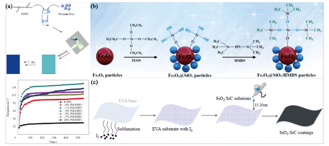
图7 (a) 超疏水涂层制备及不同普鲁士蓝添加量复合涂层光热曲线[55]; (b) Fe3O4@SiO2/HMDS粒子制备示意图[29]; (c) EVA基底上SiO2/SiC超疏水涂层制备示意图Fig. 7 (a) Preparation of the superhydrophobic coatings and photothermal curves of composite coatings added with different amount of Prussian blue[55]; (b) Schematic illustration for preparing Fe3O4@SiO2/HMDS particles[29]; (c) Schematic diagram of preparation of SiO2/SiC superhydrophobic coating onto EVA substrate |
3.2 超浸润光热材料的海水淡化及太阳能蒸发应用

图8 硅胶/MWCNT蒸发器的(a)制备示意图,(b)各组件功能,(c) 用于太阳能淡化收集水的实验装置图[58]; (d) 疏水d-Ti3C2膜制造工艺示意图;(e) 制备高效稳定太阳能淡化的一般策略[23];(f) 太阳能蒸气发电用碳烟灰涂层PAFs的合成示意图;(g) 太阳能蒸气发电蒸发器的示意图[59]Fig. 8 The (a) schematic preparation, (b) functions of each component, (c) diagram of experimental device for clean water collection via solar desalination of ilicone/MWCNT evaporators[58]; (d) The fabrication process, (e) a general strategy for efficient and stable solar desalination hydrophobic d-Ti3C2 membrane[23]; (f) schematic illustration of synthesis of carbon soot coated PAFs for solar steam generation; (g) schematic diagram of the CPAFs as evaporator for solar steam generation[59] |
3.3 超浸润光热材料的油水分离应用
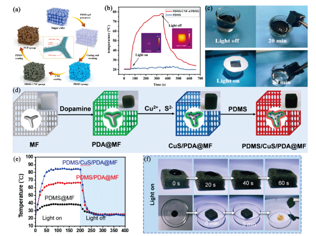
图9 (a) 泡沫复合材料的制备示意图;(b) 温度随光照时间的变化情况;(c) 无光照和有光照20 min后吸油过程的实际场景[60];(d) 超疏水PDMS/CuS/PDA@MF海绵的制备工艺示意图;(e) 不同海绵在一个太阳强度照射下的温度随时间变化图;(f) 在一个太阳强度照射下顶部到底部吸收原油滴(0.4 mL)的PDMS0.8/CuS3/PDA@MF海绵[62]Fig. 9 (a) The schematic illustration for the preparation, and (b) the temperature variation with the illumination time of the foam composite; (c) The practical scenario of the oil absorption process without and with light illumination after 20 min[60]; (d) Schematic illustration of the preparation process for a superhydrophobic PDMS/CuS/PDA@MF sponge; (e) Time-dependent temperature evolution for different sponges under one sunlight. The light was turned off after 200 s; (f) The PDMS0.8/CuS3/PDA@MF sponge for absorbing a crude oil droplet (0.4 mL) from top to bottom under one sunlight[62] |
表3 具备光热效应的超浸润材料应用简述Table 3 Brief introduction to the application of superwetting materials with photothermal effect |
| Application Type | Raw Materials | Preparation Process | Material Properties | ref |
|---|---|---|---|---|
| Remote light- driven motion | A: Multi-layered/ delaminated (m-Ti3C2Tx/ d-Ti3C2Tx) MXenes(2D) B: Fluorinated alkyl silane (FAS) C: Polydimethylsiloxane (PDMS) solution | A was prepared by chemical exfoliation process, and then A was hydrophobic modified by B, finally it was dispersed into C | Super hydrophobic; excellent photothermal conversion and capability; controllable light-driven motion | 66 |
| A:Fe3O4 NPs B: Polydimethylsiloxane (PDMS) gel C: selective lubricants | A and B were mixed,casted and peeld off to get the Fe3O4 NPs/PDMS film,then PAF were manufactured by laser ablation. | More functional and precise at controlling various UGB’s sliding speed, direction, and tracks. | 67 | |
| Droplets sorting | A: Glass slides B: Superhydrophobic coatings C: A hollowed-out glass mask D: Nano TiO2 coatings | B was sprayed onto A, then C was laminated on the surface of them, finally D were sprayed on the C. | Highthroughput separation of the target droplets with the assistance of the hydrophilic patterns and the light heating. | 68 |