


1 引言
2 电催化剂的表界面调控
2.1 基于层状双金属氢氧化物的调控
表1 不同LDH基催化剂OER性能总结Table 1 Summary of OER performance of LDH based catalysts |
| OER Catalyst | electrolyte | Current density (mA·cm-2) | Overpotential (mV) | Tafel slope (mV·dec-1) | ref |
|---|---|---|---|---|---|
| CoMn LDH | 1 M KOH | 10 | 324 | 43 | 20 |
| Porous ZnCo LDH nanosheets | 0.1 M KOH | 2 | 375 | 101 | 21 |
| NiFe LDH | 0.1 M KOH | 10 | 348 | - | 22 |
| amorphous NiFe LDH | 1 M KOH | 10 | 190 | 31 | 24 |
| NiFe LDH nanomesh | 1 M KOH | 10 | 184 | 30 | 25 |
| FeNi LDH/Ti3C2-MXene | 1 M KOH | 10 | 298 | 43 | 27 |
| FeOOH/NiFe LDH | 1 M KOH | 10 | 174 | 27 | 28 |
| NiFe LDH/Co | 1 M KOH | 20 | 300 | 62.3 | 29 |
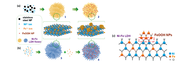
图2 (a)一锅法合成,其中(1)预先形成LDH花状中间体,随后在其上沉积FeOOH纳米颗粒以形成(2)FeOOH2 nm/LDH复合物;(b)逐步合成,其中(3)将预先形成的LDH用作优先沉积具有不同平均尺寸的FeOOH纳米颗粒的基底,以得到(4)FeOOH/LDH;(c)通过形成具有相对短键长的FeOOH纳米颗粒与NiFe LDH间的氧桥(如Fe(3 +δ)+ -O-Ni2+)形成界面相互作用的示意图[28]Fig.2 (a) One-Pot Synthesis where (1) the intermediate LDH flower is formed in the early stage, on which later FeOOH NPs are deposited to form (2) the FeOOH2 nm/LDH Composite; (b) The stepwise synthesis where (3) the preformed LDH is used as a support for preferential deposition of FeOOH NPs with various average sizes to give (4) the FeOOH/LDH; and (c) Schematic depiction of the interfacial interaction via the formation of oxygen bridges (e.g., Fe(3+δ)+-O-Ni2+) with relative short bond length between the FeOOH NPs with Ni-Fe LDH[28]. Copyright 2018, the American Chemical Society |
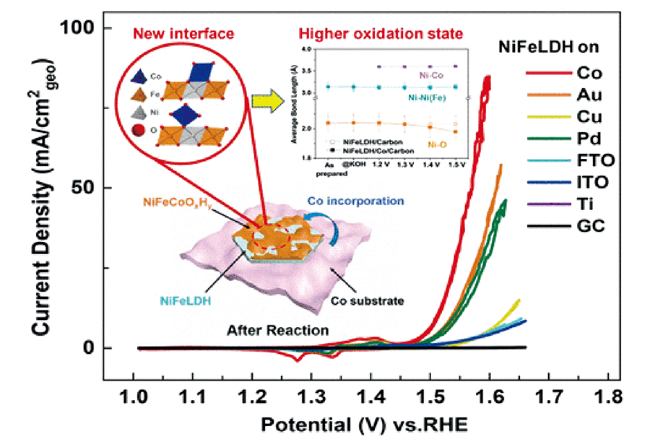
图3 NiFe LDH/Co、NiFe LDH/Au、Ni-Fe-Co三元氢氧化物和裸露的Co箔在1 mol·L-1 KOH中以10 mV/s扫速得到的CV曲线,插图表明NiFe LDH和Co箔之间的界面对提高OER活性至关重要[29]Fig.3 CVs of NiFe LDH on Co, NiFe LDH on Au, Ni-Fe-Co ternary hydroxides and bare Co foil in 1 mol·L-1 KOH at a sweeping rate of 10 mV/s, showing the interface between NiFe LDH and Co foil is crucial to enhance OER. Inset shows the schematic illustration highlighting the importance of the catalyst/support interface[29]. Copyright 2020, the American Chemical Society |
2.2 基于钙钛矿型氧化物的调控

图4 MoSe2和LSC之间的潜在相互作用机制;(a)LSC&MoSe2的HR-TEM图像,表明同时存在2H和1T相MoSe2;(b)选中的2H-MoSe2区域放大的晶格结构示意图,说明了六方晶格中Mo-Mo原子间距离为0.28 nm;(c)1T-MoSe2的扩大区域以示意晶格结构显示,表明了Mo-Mo(0.563 nm)和Se-Se(0.324 nm)的原子间距离;(d)MoSe2局部相变时从Co到Mo的电子转移示意图;(e)MoSe2和LSC之间可能的电荷转移过程示意图[38]Fig.4 Proposed mechanism describing potential interaction between MoSe2 and LSC. (a) HR-TEM image of LSC&MoSe2, indicating the presence of both 2H- and 1T-Phase MoSe2. (b) Enlarged region of 2H-MoSe2 shown with schematic lattice structure, illustrating the hexagonal crystal structure with Mo-Mo inter-atomic distance of 0.28nm. (c) Enlarged region of 1T-MoSe2 shown with schematic lattice structure, indicating the Mo-Mo (0.563nm) and Se-Se (0.324 nm) inter-atomic distances. (d) Schematic description of local phase transition in MoSe2 via electron transfer from Co to Mo. (e) Schematic diagram of proposed charge transfer processes between MoSe2 and LSC[38]. Copyright 2019, the Springer Nature |
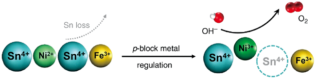
表2 不同钙钛矿催化剂OER性能总结Table 2 Summary of OER performance of perovskite based catalysts |
| OER Catalyst | electrolyte | Current density (mA·cm-2) | Overpotential (mV) | Tafel slope (mV·dec-1) | ref |
|---|---|---|---|---|---|
| LaCoO3 | 0.1 M KOH | 10 | 490 | 69 | 31 |
| LaCo0.8Fe0.2O3/NF | 0.1 M KOH | 10 | 350 | 59 | 32 |
| LaFexNi1-xO3 | 1 M KOH | 10 | 302 | 50 | 33 |
| Ba0.5Sr0.5Co0.8Fe0.2O3-δ | 0.1 M KOH | 10 | 460 | 65 | 36 |
| Nd1.5Ba1.5CoFeMnO9-δ | 0.1 M KOH | 10 | 359 | 81 | 37 |
| p-SnNiFe perovskite | 0.1 M KOH | 10 | 350 | 35 | 39 |
2.3 基于尖晶石型化合物的调控
2.4 基于合金材料的调控
表3 不同合金催化剂OER性能总结Table 3 Summary of OER performance of alloy based catalysts |