


1 引言
2 骨组织工程

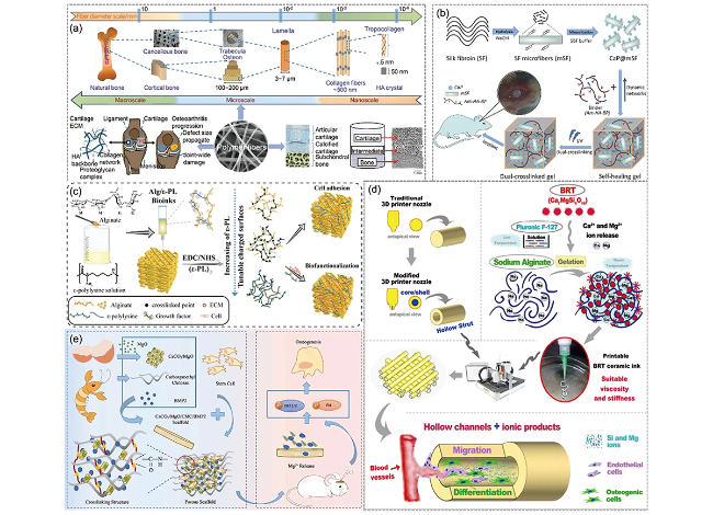
图3 (a)以聚合物纤维为支架修复骨、软骨、骨软骨缺损[18];(b)自愈合的SF基水凝胶制用于骨再生[19];(c)3D打印机械稳定、表面电荷可调的无钙海藻酸基(Alg/ε-PL)支架,以提高细胞黏附和生物功能化[20];(d)制备3D打印中空结构硅酸盐生物陶瓷支架,通过管道结构和生物活性离子的协同作用进行血管化骨再生[21];(e)CaCO3/MgO/CMC/BMP2支架的制备及其在体内的应用[22]Fig. 3 (a) Treatments of bone, cartilage, and osteochondral defects with polymer fibers as scaffolds[18]; (b) Fabrication of self-healing SF-based hydrogel for bone regeneration[19]; (c) 3D printing of mechanically stable calcium-free alginate-based (Alg/ε-PL) scaffolds with tunable surface charge to enable cell adhesion and facile biofunctionalization[20]; (d) The fabrication of the 3D-printed silicate bioceramic scaffolds with hollow struts for vascularized bone regeneration by means of the synergistic effect of the pipeline structure and bioactive ions[21]; (e) Preparation of CaCO3/MgO/CMC/BMP2 scaffolds and their applications in vivo[22] |
3 静电纺丝
3.1 静电纺丝原理

图4 (a)典型的垂直设置静电纺丝设备[24];(b)照片显示PEO悬垂液滴从球形演变为圆锥形,然后喷射出射流的过程[26];(c)静电纺丝射流的路径[26];(d)作用在带电射流上的力的示意图。受扰动区域上方的电荷推动,受扰动段受FDO向下和向外的力。同时,受到扰动区域下方的电荷的推动,被扰动的段受FUO向上和向外的力。净力FR(横向静电力)相对于笔直射流沿径向方向,并且随着段的径向位移增加,其随时间呈指数增长。FR造成射流的弯曲[26];(e)一个喷头处液滴喷出四股射流,每一股都有完善的带电弯曲线圈[26];(f)静电纺聚间苯二甲酰胺纳米纤维纱线的广角X射线衍射图[26];(g)聚乙二唑啉和荧光标记白蛋白纳米纤维的荧光显微镜图像[26]Fig. 4 (a) Typical vertical setup of electrospinning apparatus[24]; (b) Photographs showing the evolution of a pendant drop of PEO in water from a spherical to a conical shape, followed by the ejection of a jet[26]; (c) The path of an electrospun jet[26]; (d) Schematic illustration of the forces acting on a charged jet. The perturbed segment is forced by FDO downward and outward by the charges above the perturbed region. At the same time, the perturbed segment is forced by FUO upward and outward by the charges below the perturbation. The net force, FR (the lateral electrostatic force), is along a radial direction with respect to the straight jet, and it grows exponentially with time as the radial displacement of the segment increases. FR is responsible for the bending of the jet[26]; (e) Four jets from one drop, each with a well developed electrical bending coil[26]; (f) A wide angle X-ray diffraction pattern from a yarn of twisted as-spun poly (meta-phenylene isophthalamide) nanofibers[26]; (g) A fluorescence microscope image of nanofibers of poly (ethylene oxazoline) and fluorescent labeled albumin[26] |
3.2 静电纺装置及方法
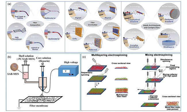
图5 (a)改变纤维组成、取向和网格结构的静电纺丝方法示意图[31];(b)用同轴静电纺丝制备核(肝素)-壳(PC/SAB-MSN)结构纤维的过程[29];(c)提出了基于多喷嘴的多层和混合静电纺丝技术[30]Fig. 5 (a) Schematics of electrospinning methods to alter fiber composition, orientation and mesh architecture[31]; (b) Process of fabricating the core (heparin)-shell (PC/SAB-MSN) fiber by coaxial electrospinning[29]; (c) Proposed material mixing strategies for multiple nozzle electrospinning[30] |
3.3 静电纺工艺参数的影响
表1 静电纺工艺、溶液和环境参数对纤维形态的影响[33,34]Table 1 Electrospinning process, solution, and ambient parameters that affect fiber morphology[33,34] |
| Parameters categories | Parameters | Effect on fiber morphology | ref |
|---|---|---|---|
| Solution Parameters | Polymer molecular weight | Irregular shape and larger pores with higher molecular weight | 35 |
| Reduction in the number of beads and droplets with increasing molecular weight | 36,37 | ||
| Solution conductivity | |||
| High voltage results in bead formation | 38 | ||
| Higher conductivity creates uniform charge density bead-free fibers with decreased fiber diameter | 39 | ||
| Solution concentration (viscosity) | |||
| High solution concentration reduces bead formation and increases fiber diameter | 40⇓⇓~43 | ||
| Low concentrations or solution viscosities yielded defects in the form of beads and junctions | |||
| Solvent volatility | |||
| High solvent volatility resulted in the blocking of the needles | 44 | ||
| Low solvent volatility yielded defects in the form of beads and junction | 44,45 | ||
| Processing Parameters | Applied voltage | High voltage results in bead formation | 46⇓~48 |
| Smaller fiber diameter with increased voltage | |||
| Working distance | A minimum distance is required to obtain dried and uniform fibers | 49 | |
| Observable beading if distance is too close or too far. | 50,51 | ||
| Solution flow rate | Smaller fiber diameter achieved with slower flow rates | 51,52 | |
| Generation of beads with too high flow rate | 53,54 | ||
| Grounded target | Metal collectors yield smoother fibers | 55,56 | |
| Porous collectors result in porous fiber and geometry structure | 38 | ||
| Needle tip design | Rotating drum collects aligned fibers | 40 | |
| Hollow fibers produced with coaxial, 2-capillary spinneret | 28 | ||
| Multiple needle tips increase throughput | 57 | ||
| Environmental Parameters | Temperature | Smaller fiber diameter results from higher temperature and decreased solution viscosity | 44 |
| Humidity | Increasing humidity resulted in the appearance of circular pores on the fibers. | 58 | |
| Air velocity | Increasing air velocity results in larger fiber diameter | 44,45 |

图6 不同静电纺参数下纳米纤维的形貌结构:(a)随机取向纳米纤维[80];(b)平行纳米纤维[74];(c)带状纤维[81];(d)树突结构纤维[82];(e)中空纳米纤维[28];(f)项链结构纳米纤维[83];(g)多孔纳米纤维[84];(h)纳米纤维空心微球[85];(i)蜂窝状纳米纤维结构[86];(j)核壳纳米纤维[87];(k)有图案的纳米纤维网[88];(l)螺旋纤维[89]Fig. 6 The morphologic structure of nanofibers under different electrospinning parameters: (a) Random orientation nanofiber[80]; (b) Parallel nanofiber[74]; (c) Ribbon-like fiber[81]; (d) Dendritic structure fiber[82]; (e) Hollow nanofiber[28]; (f) Necklace-like structure fiber[83]; (g) Porous nanofiber[84]; (h) Nanofibrous hollow microspheres[85]; (i) Honeycomb-patterned nanofibrous structures[86]; (j) Core-shell nanofiber[87]; (k) Patterned nanofiber meshes; (l) Helical fibers[89] |
4 静电纺纳米纤维的表面修饰
4.1 等离子体修饰技术
4.2 表面接枝修饰技术
4.3 表面化学修饰技术
5 静电纺丝在骨组织工程中的应用
5.1 骨缺损再生

图7 (a)从制备到动物实验的研究思路;(b)3D纳米纤维支架制备示意图;(c)PLA/Gel(A1,A2),n-HA/PLA/Gel(B1,B2), n-HA/PLA/Gel-PEP(C1,C2)三维支架修复大鼠颅骨缺损(直径=6 mm)术后4周和8周的Micro-CT图像;(d)不同样本组(术后8周)的H&E染色图像。蓝色箭头表示新的骨骼,绿色箭头表示宿主骨骼;(e)不同样本组(术后8周)的Masson三色染色图像。红色箭头表示新骨,绿色箭头表示宿主骨,黑色箭头表示剩余支架Fig. 7 (a) Research ideas from preparation to animal experiment; (b) Schematic of 3D nanofibrous scaffold preparation; (c) Micro-CT images of rat cranial bones defects (diameter = 6 mm) repaired by PLA/Gel (A1, A2), n-HA/PLA/Gel (B1, B2), and n-HA/PLA/Gel-PEP (C1, C2) 3D scaffolds 4 and 8 weeks after surgery; d) H&E stained images of different sample groups (8 weeks after surgery). Blue arrows indicate new bone, and green arrows indicate host bone; (e) Masson’s trichrome stained images of different sample groups (8 weeks after surgery). Red arrows indicate new bone, green arrows indicate host bone, and black arrows indicate residual scaffolds |
5.2 软骨缺损修复

图8 (a)静电纺丝纤维增强CDM基3D打印支架用于软骨再生的示意图;(b)兔关节软骨修复的实验研究,术后12周,不同组软骨关节的宏观图像Fig. 8 (a) Schematic illustration of electrospinning fiber-reinforced CDM-based 3D-printed scaffold for cartilage regeneration; (b) Articular cartilage repair in rabbits. Macroscopic images of the cartilage joints from different groups at 12 weeks after surgery |
5.3 骨软骨组织工程

图9 (a)双层COL支架(左上)和COL-纳米纤维支架(右上)的制备过程;(b)术后6周和12周,观察三组软骨关节的大体图像及ICRS评分:(A,D)未处理组、(B,E)COL组和(C,F)COL-纳米纤维组;(c)术后12周取材进行组织学检查,苏木精-伊红(A-F)和藏红O(G-L)染色。每幅图像中都用黑色箭头表示缺陷;(d)术后12周对修复组织的结构进行评价:未治疗组(B组)、COL组(C组)、COL-纳米纤维组(D组)和正常关节组(E)的μ-CT图像Fig. 9 (a) Fabrication process of bi-layer COL scaffolds (top left) and COL-nanofiber scaffolds (top right); (b) Macroscopic images of the cartilage joints from three groups and their ICRS scores at 6 and 12 weeks after surgery. (A, D) non-treated group, (B, E) COL group and (C, F) COL-nanofiber group; (c) Histological examination of samples from three groups at 12 weeks after surgery, stained with hematoxylin and eosin (A-F) and Safranin O (G-L). The defect is indicated with black arrows in each image; (d) Architecture evaluation of the repaired tissues at 12 weeks after surgery: μ-CT images of tissues from non-treated group (B), COL group (C), COL-nanofiber group (D) and normal joints (E) |