


Contents
1 引言
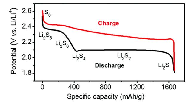
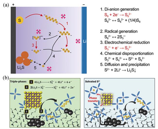
2 工作原理及问题
 8Li2S
8Li2S 8Li2S
8Li2S Li+ + e-
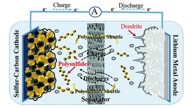
3 催化机理及材料
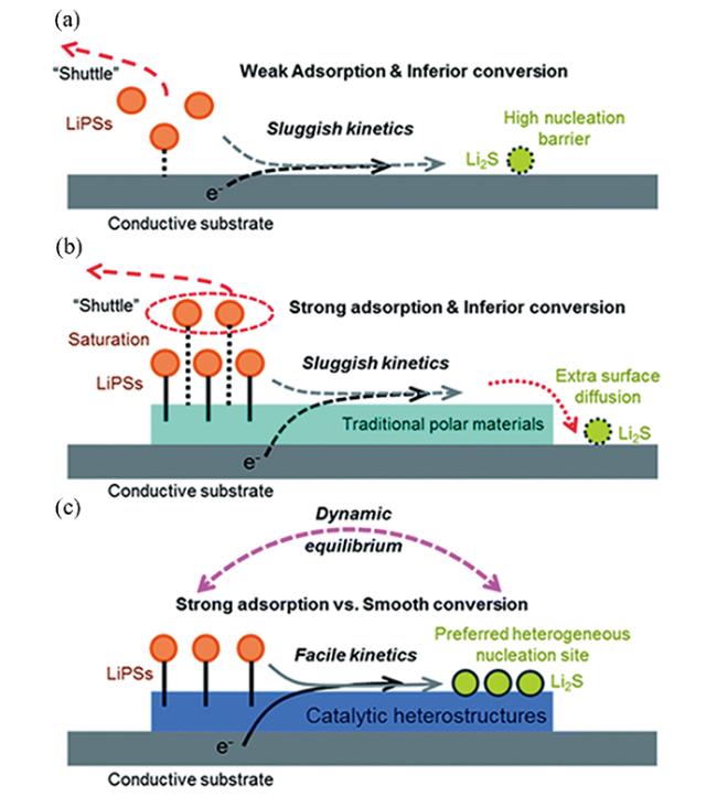
3.1 吸附-转化机制
3.1.1 还原过程中的催化机制
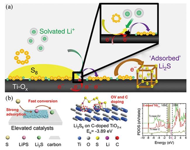
图5 (a)Ti4O7表面介导LiPS还原反应[17];(b)富缺陷的异质结电催化剂的催化机理、与Li2S6的相互作用示意图及Ti和C的局域态密度分析[39]Fig.5 (a) Surface-mediated reduction of Li2S from LiPSs on Ti4O7[17];(b) Schematic illustration of catalytic mechanism of defect-rich heterojunction electrocatalyst and its interaction with Li2S6, as well as the partial density of states analysis of Ti and C[39] |
3.1.2 氧化过程中的催化机制
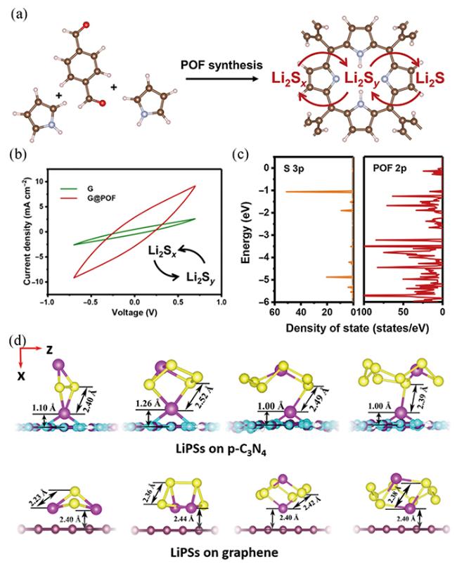
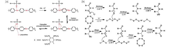
图9 (a)POF的合成及其表面LiPSs催化示意图[75];(b)可溶性LiPSs之间转化的CV曲线(2 < y < x ≤ 8) [75];(c)Li2S6中硫的3p轨道和POF中碳和氮的2p轨道的态密度分析[75];(d)LiPSs在p-C3N4和石墨烯表面的分子构型[78]Fig.9 (a) Schematic illustration of POF synthesis and polysulfides catalysis on it[75];(b) CV curve of conversion between soluble LiPSs(2 < y < x ≤ 8) [75];(c) Density of states analysis of sulfur 3p orbitals in Li2S6 and carbon and nitrogen 2p orbitals in POF[75];(d) Molecular configuration of LiPSs on the surface of p-C3N4 and graphene[78] |
3.1.3 双功能催化机制
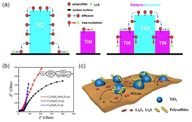
图10 (a)TiN、TiO2、TiO2-TiN异质结表面的LiPSs转化过程示意图[79];(b)C@SnS2/S、C@SnO2/S、C@SNS2/SnO2/S的电化学阻抗谱[81];(c)LiPSs在TiO2-Ti3C2Tx异质结表面吸附-转化过程示意图[85]Fig.10 (a) Schematic illustrations of LiPSs conversion process on the surface of TiN, TiO2 and TiO2-TiN heterojunction[79];(b) Electrochemical impedance spectroscopy of C@SnS2/S, C@SnO2/S and C@SNS2/SnO2/S[81];(c) Schematic illustration of LiPSs adsorption-conversion process on the TiO2-Ti3C2Tx heterostructures[85] |
3.2 氧化还原介导机制
3.2.1 硫代硫酸盐/聚硫酸盐介导
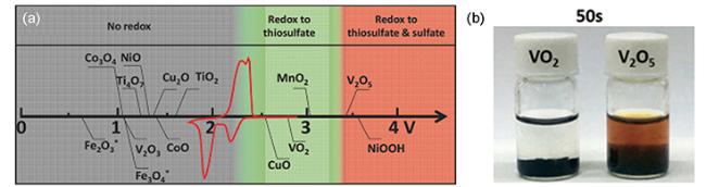
图12 (a)不同金属氧化物与LiPSs的反应活性(图中电位相对于Li/Li+,红色曲线为Li-S循环伏安曲线)[98];(b)VO2和V2O5的Li2S6吸附性能测试[99]Fig.12 (a) Reactivity of different metal oxides with LiPSs(the potential in the figure is relative to Li/Li+, the red curve is the Li-S cyclic voltammetry curve)[98];(b) Li2S6 adsorption test of VO2 and V2O5[99] |
3.2.2 硫自由基介导
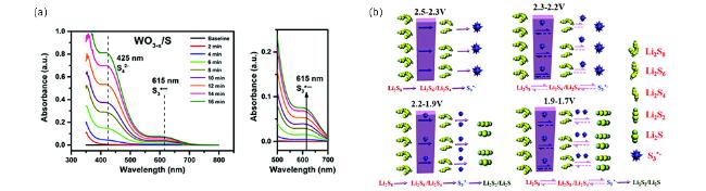
图14 (a)含WO3-x和WO3的阴极放电至2.35 V并保持不同时间的紫外可见光谱[115];(b)CNTs-S/TS-1阴极自由基介导的LiPSs转化过程[116]Fig.14 (a) UV-vis spectra of sulfur cathodes with WO3-x and WO3 nanoplates discharged to 2.35 V and held for different times[115];(b) Schematic illustration of the radicals-mediated LiPSs conversion process in CNTs-S/TS-1 cathode[116] |
3.2.3 氧化还原电对介导
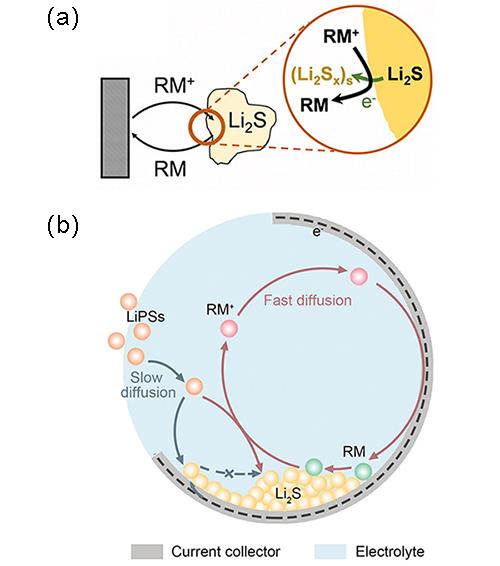
图15 (a)锂硫电池中直接氧化(上图)和RM介导氧化(下图)示意图[117];(b)锂硫电池中直接还原(蓝色箭头)和RM介导还原(红色箭头)示意图[118]Fig.15 (a) Schematic illustration of direct oxidation(above) and RM-mediated oxidation(below) in lithium-sulfur batteries[117];(b) Schematic illustration of direct reduction(blue arrow) and RM-mediated reduction(red arrow) in lithium-sulfur batteries[118] |
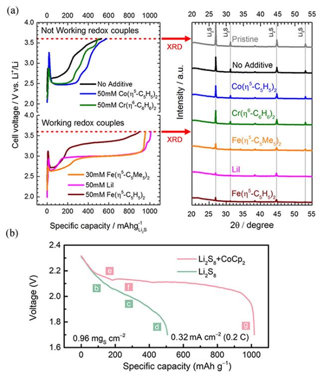
图16 (a)在含有不同RM的电解液中恒电流充电的Li2S阴极电压曲线,及截止电压处的阴极XRD表征[117];(b)含有RM和不含RM的锂硫电池首周放电曲线[118]Fig.16 (a) Voltage profiles of Li2S cathode charged with constant current in electrolytes with different RMs, and XRD characterization of the cathode at the cut-off voltage[117];(b) The first discharge profile of lithium-sulfur battery with or without RM[118] |
3.3 其他催化机制
3.3.1 单原子催化
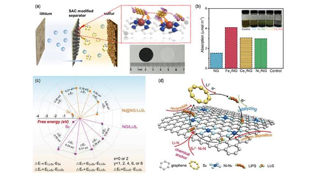
图18 (a)M1/NG(M=Fe、Co、Ni)修饰隔膜示意图(插图为修饰前后隔膜的数码照片)[130];(b)在DOL/DME中NG和M1/NG表面Li2S6吸附的电化学滴定实验(插图为滴定溶液静置12 h后的数码照片)[130];(c)LiPSs在NG和Ni@NG表面的自由能示意图[131];(d)LiPS在Ni@NG表面的催化机理[131]Fig.18 (a) Schematic illustration of the preparation of the M1/NG-modified separator(Inset: digital photo of separators before and after modification)[130];(b) Electrochemical titrations of the Li2S6 adsorption on NG and M1/NG in DOL/DME(Inset: digital photo of the titrated solutions after 12 hours)[130];(c) The free-energy diagrams of LiPSs on NG or Ni@NG[131];(d) The catalytic mechanism of the LiPSs on the surface of Ni@NG[131] |
3.3.2 有机硫化学及硫醇化学
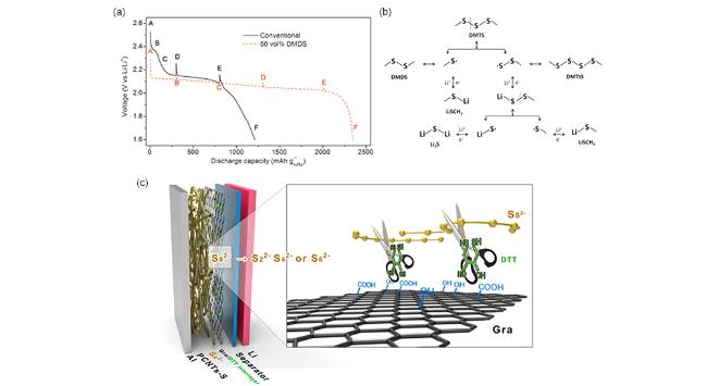
图20 (a)具有常规电解液和含50 vol% DMDS电解液的烧瓶锂硫电池首周放电曲线[135];(b)三甲基二硫化物(DMTS)的氧化还原反应机理示意图[136];(c)带有Gra/DTT中间层的Li-S电池结构及功能示意图[137]Fig.20 (a) Initial discharge profiles of the flask cells with conventional and 50 vol% DMDS-containing electrolyte[135];(b) The redox mechanism of trimethyl disulfide(DMTS)[136];(c) Schematic illustration of structure and function of the LSB with Gra/DTT interlayer[137] |
4 催化机制的表征技术与研究方法
4.1 电化学测试
4.2 材料与结构表征
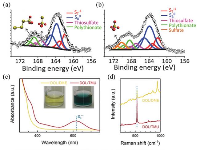
图21 (a)CuO-Li2S4悬浊液中回收固体的XPS谱图[98];(b)NiOOH-Li2S4悬浊液中回收固体的XPS谱图[98];(c)Li2S6在不同溶剂中的UV-vis光谱[109];(d)Li2S6溶液在不同溶剂中的拉曼光谱[109]Fig.21 (a) XPS spectra of solids recovered from CuO-Li2S4 suspension[98];(b) XPS spectra of solids recovered from NiOOH-Li2S4 suspension[98];(c) UV-vis spectra of Li2S6 in different solvents[109];(d) Raman spectra of Li2S6 in different solvents[109] |
4.3 理论模拟方法
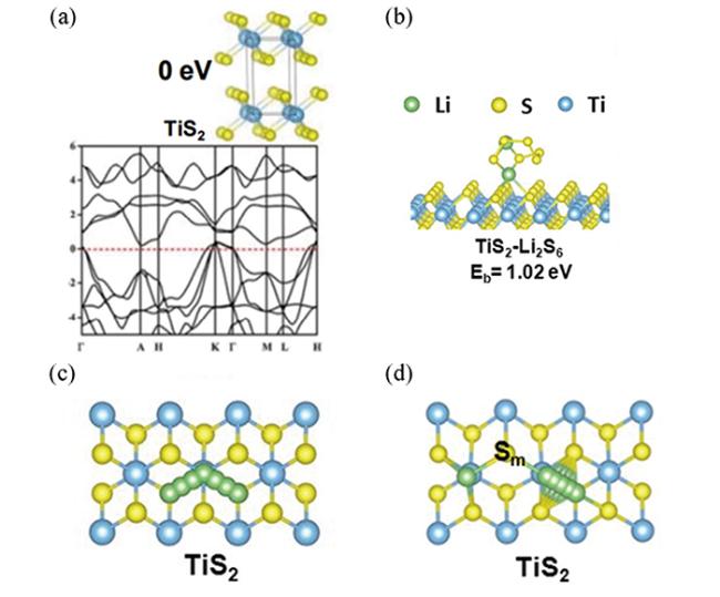
图22 (a)TiS2的晶体结构和理论能带结构[14];(b)Li2S6在TiS2表面的吸附模拟[14];(c)Li+在TiS2表面的扩散路径示意图[14];(d)Li2S在TiS2表面的分解途径示意图[14]Fig.22 (a) Crystal structure and theoretical band structure of TiS2[14];(b) Simulation of Li2S6 adsorption on the surface of 2[14];(c) Schematic illustration of the diffusion path of Li+ on the surface of 2[14];(d) Schematic illustration of Li2S decomposition on the surface of 2[14] |