


1 引言
2 铅卤钙钛矿-聚合物复合材料的制备
2.1 共混法
2.1.1 共混法制备复合薄膜材料
2.1.2 共混法制备复合纤维材料
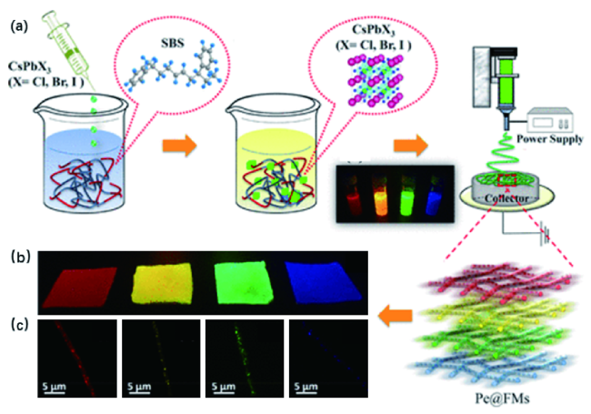
图2 (a)CsPbX3@SBS纤维膜制造工艺示意图;(b)红、黄、绿和蓝色复合纤维膜在紫外光激发下的光学图像;(c)多功能CsPbX3光纤的荧光显微图像[52]Fig.2 (a) Schematic of CsPbX3@SBS fiber membranes(FMs) fabrication process.(b) Optical image of red, yellow, green, and blue composite FMs under UV-light excitation.(c) Fluorescence microscopic images of versatile CsPbX3 fibers[52] |
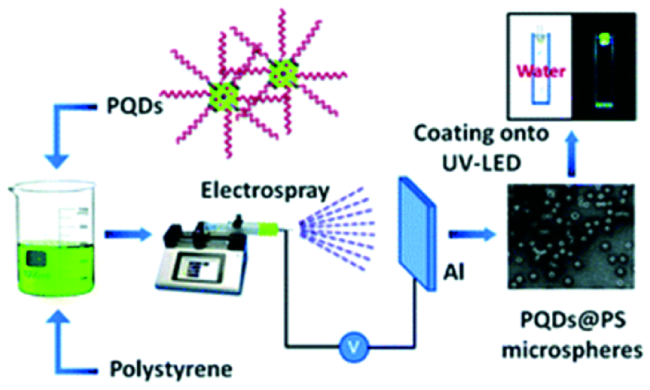
2.1.3 共混法制备单分散微米/纳米复合材料
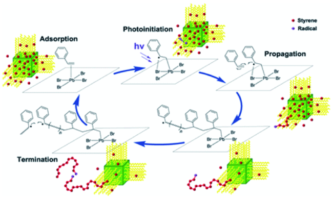
2.2 原位聚合法
2.3 原位钙钛矿生长/沉淀法
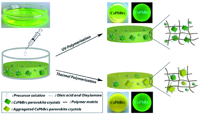
2.3.1 原位钙钛矿生长/沉淀法制备复合薄膜和块体材料
2.3.2 原位钙钛矿生长/沉淀法制备复合纤维材料
2.3.3 原位钙钛矿生长/沉淀法制备单分散纳米复合材料
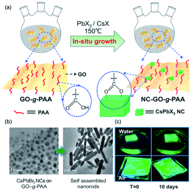
图7 (a)三元NC-GO-g-PAA杂化物的合成;(b) NC-GO-g-PAA杂化物和自组装纳米棒的TEM图像;(c) 涂有NC-GO-g-PAA纳米棒薄膜的玻片在水中浸泡或暴露于空气中0和10 d的照片[67]Fig.7 (a) Illustration of the Synthesis of Ternary NC-GO-g-PAA Hybrid.(b)TEM images of the NC-GO-g-PAA hybrid and self-assembled nanorods.(c) Photographs of glass slides coated with NC-GO-g-PAA nanorod films after soaking in water or exposure to air for 0 and 10 days[67] |
3 钙钛矿-聚合物复合材料的应用
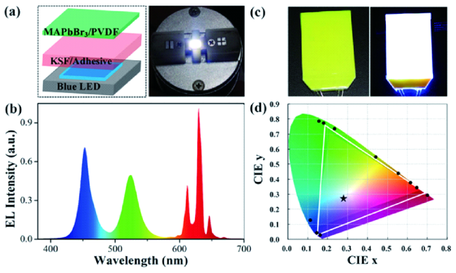
图8 (a)发光二极管器件制备图和白色发光二极管照片;(b)白色发光二极管的发射光谱;(c)尺寸为3.5 cm×5 cm的复合薄膜背光系统演示;(d)获得的白色发光二极管在CIE 1931图中的颜色坐标(黑星)和颜色三角形(白线)[58]Fig.8 (a) Schematic diagram of the configuration of the prototype LED device and photographs of white LED;(b) Emission spectrum of the white LED;(c) A demonstration of composite films based backlight system with a size of 3.5 cm × 5 cm.(d) The color coordinate(black star) and the color triangle(white line) of obtained white LED is exhibited in CIE 1931 diagram[58] |
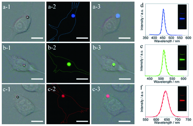
图9 (a,b,c-1)和(-2)CsPbX3 NCs@MHSs孵育的RAW 264.7细胞的亮场和荧光图像;(a,b,c-3)是(-1)(-2)的叠加照片;(d~f)CsPbX3 NCs@MHSs(虚线)和相应的NCs胶体溶液(实线)的荧光谱图[69]Fig.9 (a, b, c-1) and(-2) Bright-field and fluorescence images of RAW 264.7 cells incubated with CsPbX3 NCs@MHSs.(a, b, c-3) Overlaid picture of(-1) and(-2).(d~f)The PL spectra of intracellular CsPbX3[69] |