


1 引言
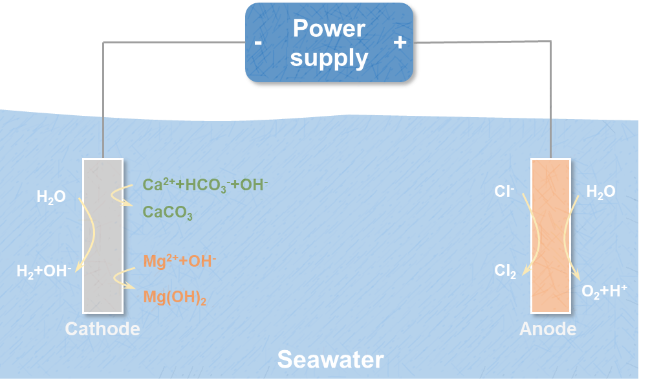
2 电解海水制氢原理
2.1 阴极析氢反应
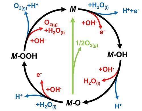
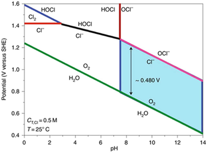
2.2 阳极析氧反应
3 电解海水制氢存在的问题与挑战

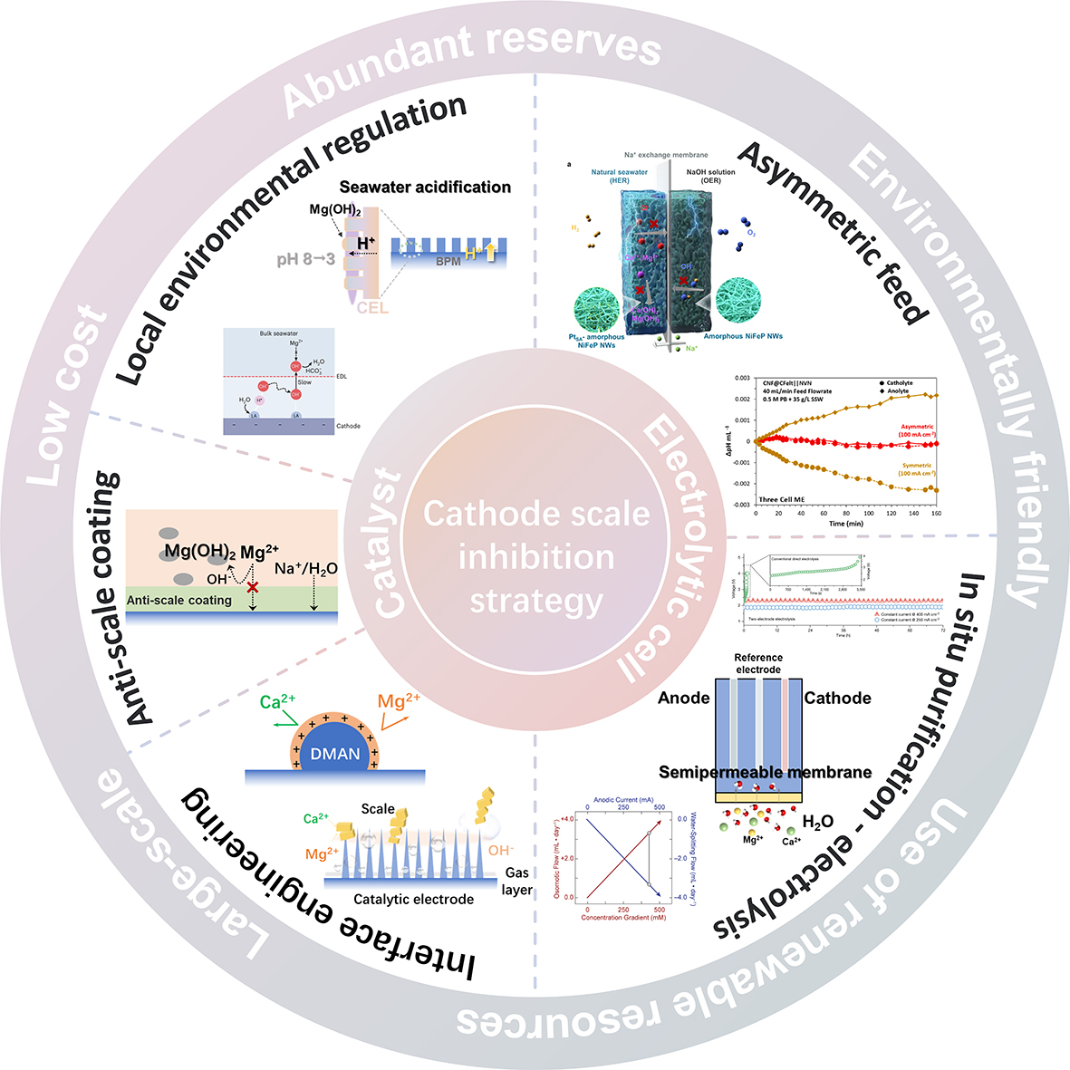
4 直接电解海水阴极碱垢的形成机制及抑制方法
4.1 阴极无机沉淀的形成机制
4.2 高性能HER催化剂
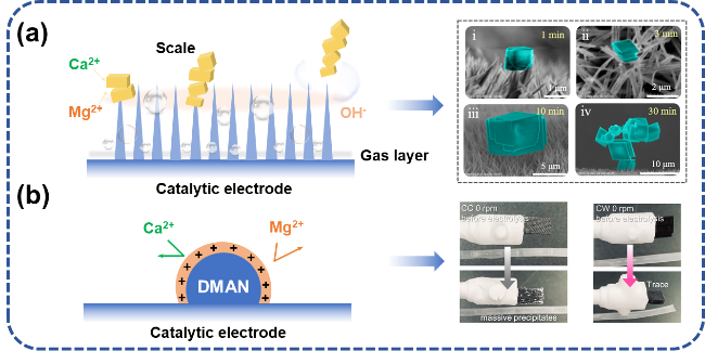
图5 电解海水催化剂阻垢设计:(a) 纳米结构增强氢气泡传质过程,通过氢气泡破裂除垢[35];(b) 引入质子海绵排斥Ca2+、Mg2+[44]Fig. 5 Scale inhibition design of electrolytic seawater catalyst. (a) The nanostructure enhances the hydrogen bubble mass transfer process and removes scale through the hydrogen bubble rupture[35]. (b) The introduction of proton sponge repels Ca2+ and Mg2+[44].Copyright 2024,Elsevier |
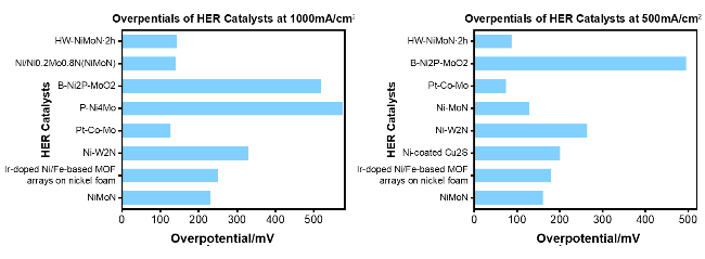
表2 大电流密度下部分海水电解制氢HER催化剂过电位比较[51]Table 2 Comparison of overpotentials for HER catalysts in partial seawater electrolysis for hydrogen production at high current densities[51] |
| HER catalyst | Electrolyte | Overpotential | Max current density | Ref |
|---|---|---|---|---|
| NiMoN | 1.0 M KOH + seawater | 82 mV @100 mA·cm-2 160 mV @500 mA·cm-2 218 mV @1000 mA·cm-2 | 1000 mA·cm-2 | 52 |
| Ir-doped Ni/Fe-based MOF arrays on nickel foam | 1.0 M KOH + seawater | 180 mV @500 mA·cm-2 238 mV @1000 mA·cm-2 | 1000 mA·cm-2 | 53 |
| Cu2S@Ni | 1.0 M KOH + seawater | 200 mV @500 mA·cm-2 | 500 mA·cm-2 | 54 |
| Ni-W2N | 1.0 M KOH + seawater | 265 mV @500 mA·cm-2 310 mV @1000 mA·cm-2 345 mV @1500 mA·cm-2 | 1500 mA·cm-2 | 55 |
| Ni-MoN | 1.0 M KOH + seawater | 29 mV @10 mA·cm-2 66 mV @100 mA·cm-2 128 mV @500 mA·cm-2 | 500 mA·cm-2 | 56 |
| Pt-Co-Mo | 1.0 M KOH + seawater | 25 mV @100 mA·cm-2 74 mV @500 mA·cm-2 117 mV @1000 mA·cm-2 194.1 mV @2000 mA·cm-2 | 2000 mA·cm-2 | 57 |
| P-Ni4Mo | 1.0 M KOH + seawater | 260 mV @100 mA·cm-2 551 mV @1000 mA·cm-2 | 1000 mA·cm-2 | 58 |
| B-Ni2P-MoO2 | 1.0 M KOH + seawater | 29 mV @10 mA·cm-2 50 mV @50 mA·cm-2 64 mV @100 mA·cm-2 91 mV @200 mA·cm-2 496 mV @500 mA·cm-2 | 500 mA·cm-2 | 59 |
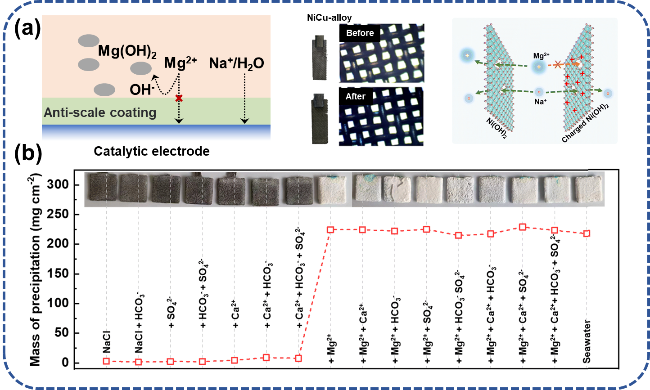
4.3 电极保护层
表3 电极保护层阻垢策略实际测试环境Table 3 Practical testing environment for electrode protection layer anti-scaling strategy |
4.4 海水局部反应条件调控
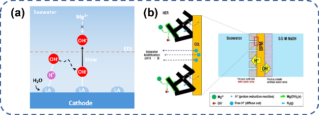
图8 电解海水局部反应条件调控阻垢设计:(a) 路易斯酸层捕捉OH-实现局部碱化[62];(b) 多孔阴极/双极膜界面传输H+实现局部酸化[15]Fig. 8 Local reaction conditions of electrolytic seawater control scale inhibition design. (a) The Lewis acid layer captures OH- to achieve local alkalization[62].Copyright 2023,Springer Nature; (b) The porous cathode/bipolar membrane interface transmits H+ to achieve local acidification[15].Copyright 2022,John Wiley and Sons |
4.5 极性互换
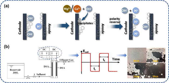
图9 极性互换去除电极表面水垢:(a) 除垢机理示意图;(b) 极性互换电解装置及其在150 A·m-2电流密度下交流电解3 min电极表面水垢沉积变化[64]Fig. 9 Polarity reversal to remove scale on electrode surface. (a) Schematic diagram of descaling mechanism. (b) Polarity reversal electrolysis device and its change of scale deposition on electrode surface in AC electrolysis for 3 min at 150 A·m-2 current density[64]. Copyright 2019,Elsevier |
4.6 电解池和电解体系设计
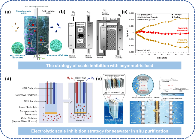
图12 低温海水电解槽阻垢设计:(a) 不对称进料缓解碱垢沉积[71];(b) 改进传统电解液循环路径,将阳极液供给阴极室以降低pH上升[72];(c) 对称/不对称进料方式阴极室pH变化趋势[74];(d) FO技术实现盐水的原位净化电解[75];(e) “液-固-液”相变机制实现海水原位净化电解[77]Fig. 12 Scale inhibition design of low temperature seawater electrolytic cell. (a) Asymmetric feeding alleviates alkaline scale deposition[71]. (b) The traditional electrolyte circulation path is improved and the anodic solution is fed to the cathode chamber to reduce the pH rise[72]. Copyright 2008,Springer Nature. (c) Trend of pH change in cathode chamber of symmetric/asymmetric feeding mode[74]. Copyright 2024,Elsevier. (d) The “liquid-solid-liquid” phase change mechanism realizes in situ purification and electrolysis of seawater[75]. (e) “Liquid-Solid-Liquid” phase transition mechanism enabling in situ seawater purification via electrolysis[77]. Copyright 2022,Springer Nature |