


1 引言
2 MOFs在储能领域应用
2.1 锂离子电池中的应用
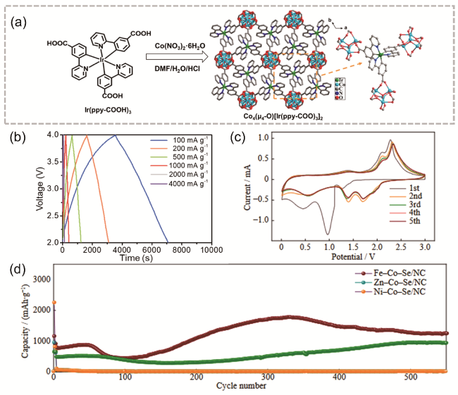
图1 (a) Co4-Ir MOF合成与结构示意图;(b) HLIC在不同电流密度下从100到4000 mA·g-1的恒电流充放电曲线[26];(c) Fe-Co-Se/NC的CV曲线;(d) Fe-Co-Se/NC与其他两个对照组在1 A·g-1时的循环性能图[27]Fig. 1 (a) Synthesis and structure diagram of Co4-Ir MOF, (b) HLIC constant current charge-discharge curves from 100 to 4000 mA·g-1 at different current densities [26]. Copyright 2021 Wiley-VCH GmbH, (c) cyclic voltammetry of Fe-Co-Se/NC, (d) Fe-Co-Se/NC cycling performance plot at 1 A·g-1 with two other control groups [27]. Copyright 2023, University of Science and Technology Beijing |
2.2 钠离子电池中的应用
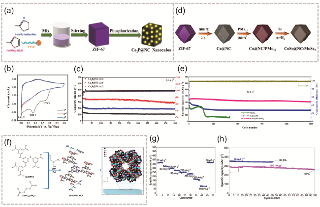
图2 (a) Co2P@NC制备方法;(b) 0.1 mV·s-1扫描速率下Co2P@NC-12.5的CV曲线;(c) 3种对比条件的Co2P@NC电流密度为0.1 A·g-1时的充放电稳定性[33];(d) CoSe@NC/MoSe2制备过程;(e) CoSe@NC/MoSe2与对照电极在5.0 A·g-1下的长期循环稳定性[34];(f) Zn-TDPAT MOF的合成和结构;(g) Zn-TDPAT-GC倍率性能;(h) 在20 mA·g-1和100 mA·g-1下Zn-TDPAT-GC电极的循环性能测试[35]Fig. 2 (a) Co2P@NC preparation method, (b) Cyclic voltammetry curve of Co2P@NC-12.5 at 0.1 mV·s-1 scan rate, (c) Charge-discharge stability of Co2P@NC at a current density of 0.1 A·g-1 under three comparison conditions[33]. Copyright 2023 Elsevier B.V. All rights reserved, (d) CoSe@NC/MoSe2 preparation method, (e) CoSe@NC/MoSe2 long-term cycling stability with reference electrode at 5.0 A·g-1 [34].Copyright 2023 Elsevier B.V. All rights reserved. (f) Zn-TDPAT MOF synthesis process and structure diagram, (g) Zn-TDPAT-GC magnification performance, (h) cycling performance test of Zn-TDPAT-GC electrode at current densities of 20 mA·g-1 and 100 mA·g-1 [35]. Copyright 2023 Elsevier Ltd. All rights reserved |
2.3 钾离子电池中的应用

图3 (a) Co-MOF-rGO杂化材料的制备示意图;(b) Co- MOF-rGO复合负极材料电化学性能测试图[40];(c) Bi@N-CNCs产物的合成过程[42];(d) 3D结构Bi-MOF的制备[39];(e) Bi/Bi3Se4@CNR的合成过程[43]Fig. 3 (a) Co-MOF-rGO preparation process; (b) Electrochemical performance test of composite anode material Co-MOF-rGO[40]. Copyright 2020, American Chemical Society, (c) Bi@N-CNCs preparation process [42]. Copyright 2020 Wiley-VCH GmbH. (d) 3D structure Bi-MOF preparation process [39]. Copyright 2023 Wiley-VCH GmbH. (e) Bi/Bi3Se4@CNR preparation process [43]. Copyright 2023 Science Press and Dalian Institute of Chemical Physics, Chinese Academy of Sciences. Published by ELSEVIER B.V. and Science Press. All rights reserved |
2.4 碱金属-硫属电池中的应用
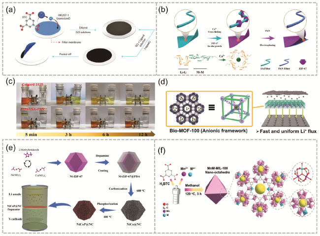
图4 (a) MOF@GO隔膜的制备过程[46];(b) ZIF-67/ SA-PAN的合成过程;(c) Celgard2325和ZIF-67/SA-PAN隔膜的多硫化物渗透测试对比[47];(d) Bio-MOF-100诱导锂均匀沉积的方案[49];(e) NiCoP@NC改性隔膜的制备过程[50];(f) MnM-MIL-100的制备(其中,M代表掺入的次级金属离子)[52]Fig. 4 (a) Preparation process of MOF@GO separator[46]. Copyright 2016, Springer Nature Limited, (b) ZIF-67/SA-PAN preparation process, (c) Comparison of polysulfide penetration tests for separator Celgard2325 and ZIF-67/SA-PAN [47]. Copyright 2022, American Chemical Society, (d) Scheme of uniform lithium deposition induced by Bio-MOF-100[49]. Copyright 2021, American Chemical Society. (e) Preparation process of NiCoP@NC separator [50]. Copyright 2023 Elsevier Inc. All rights reserved. (f) MnM-MIL-100 preparation process (here M represents the secondary metal ions incorporated into the metal-organic linker molecule)[52]. Copyright 2021 Wiley-VCH GmbH |
2.5 水系锌离子电池中的应用
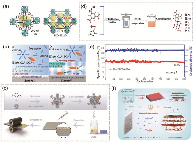
图5 (a) UiO-67-3D和UiO-67-2D的晶体结构[56];(b) Zn表面演变示意图[57];(c) D-UiO-66层的合成路线[58];(d) Mn-H3BTC-MOF-4中Mn(Ⅱ)的合成过程及配位环境;(e) Mn-H3BTC-MOF-4在3000 mA·g-1下的循环性能[60];(f) 二维CuHHTP/MX异质结构与Zn/Cu-HHTTP/MX电池机理示意图[61]Fig. 5 (a) Crystal structure of UiO-67-3D and UiO-67-2D [56]. Copyright 2022, Science China Press and Springer-Verlag GmbH Germany, part of Springer Nature. (b) Schematic illustration of Zn surface evolution [57]. Copyright 2020 Wiley-VCH Verlag GmbH & Co. KGaA, Weinheim. (c) Preparation process of D-UiO-66 [58]. Copyright 2023, The Author(s). (d) Diagrammatic sketch of the synthetic procedure and coordination environment of Mn(II) in Mn-H3BTC-MOF-4, (e) cycling performance of Mn-H3BTC-MOF-4 at 3000 mA·g-1 [60]. Copyright 2021, American Chemical Society. (f) schematic illustration of the formation of 2D CuHHTP/MX heterostructure and the mechanism of Zn/Cu-HHTP/MX batteries [61]. Copyright 2022 Wiley-VCH GmbH. |
2.6 超级电容器中的应用
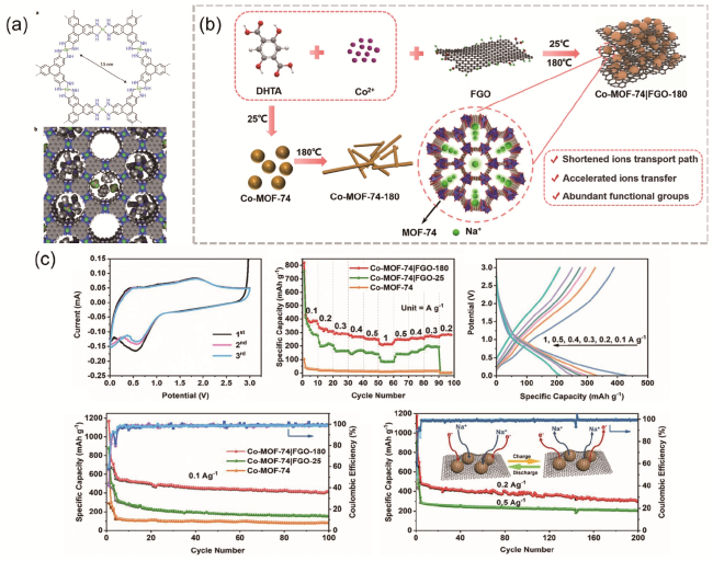
图6 (a) Ni3(HITP)2的分子结构与理想空间填充图[64];(b) Co-MOF-74|FGO-180的合成过程;(c) Co-MOF-74|FGO-180电极与参比电极电化学性能测试图[66]Fig. 6 (a) Ni3(HITP)2 molecular structure and ideal space filling diagram [64].Copyright 2016, Springer Nature Limited. (b) Preparation process of Co-MOF-74|FGO-180, (c) Electrochemical performance test diagram of Co-MOF-74|FGO-180 electrode and reference electrode [66]. Copyright 2022 Elsevier B.V. All rights reserved |
3 MOFs及其衍生材料的改性策略
3.1 MOFs的本征调控
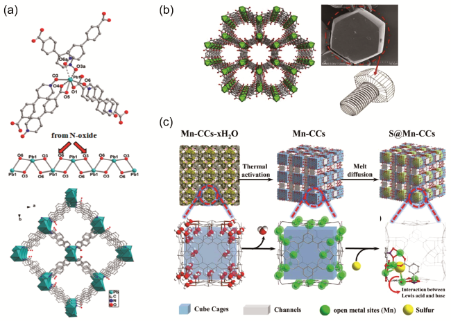
图7 (a) Pb2+离子的配位几何结构,[PbO2]∞链与沿c轴的一维通道的多面体的3D框架[69];(b) Ti-MOF电极的结构[70];(c) S@Mn-CCs合成及分子笼状结构示意图[71]Fig. 7 (a) Coordination geometry of Pb2+ ion, [PbO2]∞ chain and 3D framework with the highlighted polyhedra showing the 1D channels along the c-axis[69].Copyright 2017, Ameri can Chemical Society. (b) Structure of the Ti-MOF electrode[70]. Copyright 2018 Elsevier Ltd. All rights reserved. (c) Schematic diagram of S@Mn-CCs synthesis and molecular cage structure[71]. Copyright 2019 Royal Society of Chemistry |
表1 原始MOFs材料应用于二次电池性能Table 1 Pristine MOFs for battery |
| Pristine MOFs | Application | Cycle number | Reversible capacity | ref |
|---|---|---|---|---|
| Ni-MOF | LIBs | 100 | 620 mAh·g-1 at 100 mA·g-1 | 78 |
| Mn-CCs | LSBs | 200 | 990 mAh·g-1 at 0.2 C | 71 |
| Fe-BTC | LIBs | 100 | 1021 mAh·g-1 at 100 mA·g-1 | 79 |
| Pb-MOF | LIBs | 500 | 489 mAh·g-1 at 100 mA·g-1 | 69 |
| Mn-BTC | LIBs | 100 | 694 mAh·g-1 at 103 mA·g-1 | 68 |
| Ti-MOF | LIBs | 50 | 527.12 mAh·g-1 at 100 mA·g-1 | 70 |
| Zn-MOF | LSBs | 200 | 609 mAh·g-1 at 0.2 C | 80 |
| ZIF-7 | ZIBs | 20/180 | 188.4 mAh·g-1/129.1 mAh·g-1 at 500 mA·g-1 | 81 |
| MIL-53 | LIBs | 50 | 71 mAh·g-1 at 0.2 C | 82 |
| MIL-68 | LIBs | 12 | 32 mAh·g-1 at 0.2 C | 83 |
| MIL-100(Cr) | LSBs | 60 | ~450 mAh·g-1 at 0.1 C | 84 |
| Fe-MIL-88B | LIBs | 400 | 744.5 mAh·g-1 at 60 mA·g-1 | 85 |
| MIL-47 | LIBs | 50 | 70 mAh·g-1 at 10 mA·g-1 | 86 |
| MIL-88A | LSBs | 1000 | 300 mAh·g-1 at 0.5 C | 87 |
| MIL-125 | PIBs | 200 | 157 mAh·g-1 at 50 mA·g-1 | 88 |
| ZIF-8 | LSBs | 300 | 553 mAh·g-1 at 0.5 C | 89 |
3.2 MOFs衍生碳材料
3.2.1 多孔碳材料
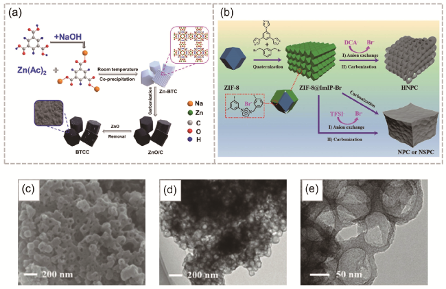
图8 (a) BTCC制备流程[92];(b) HNPC、NPC和NSPC合成;(c-e) HNPC-900的SEM与TEM图[93]Fig. 8 (a) Preparation process of BTCC [92]. Copyright 2021 Elsevier Inc. All rights reserved. (b) Preparation process of HNPC, NPC and NSPC, (c-e) SEM and TEM diagrams of HNPC-900 [93]. Copyright 2019 WILEY-VCH Verlag GmbH & Co. KGaA, Weinheim |
3.2.2 多级结构

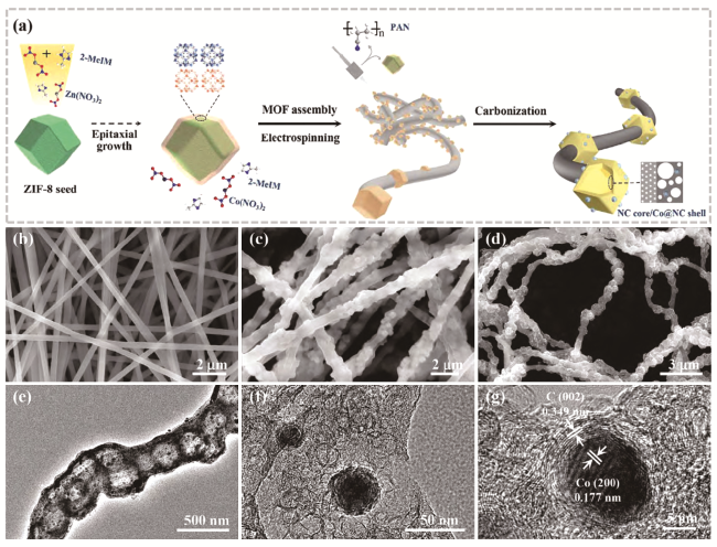
图10 (a) 制备Co@N-HPCFs催化剂的示意图;(b~d) PAN纳米纤维、MOFs/PAN纳米纤维和Co@N-HPCF-800的SEM图像;(e~g) Co@N-HPCF-800的TEM和HRTEM图像[105]Fig. 10 (a) Schematic illustration for preparing Co@N- HPCFs catalyst. SEM images of (b) PAN nanofibers, (c) MOFs/PAN nanofibers, and (d) Co@N-HPCF-800. (e~g) TEM and HRTEM images of Co@N-HPCF-800[105]. Copyright 2022 Science Press and Dalian Institute of Chemical Physics, Chinese Academy of Sciences. Published by ELSEVIER B.V. and Science Press. All rights reserved. |
3.2.3 其他结构

图11 (a) NiCo@HCS合成[107];(b) CoNiSe2/C纳米球的合成以及Ni-Co-MOF、Ni-MOF和Co-MOF的SEM和TEM图像[108];(c) SEM、粉末X射线衍射(PXRD)图谱、花状Zn-TDPAT纳米片模型,以及Zn-TDPAT纳米片在900 ℃下衍生的花状微孔氮掺杂碳纳米片(FMNCN-900)[109];(d) 碳化前的Co-SCPC以及Co-SCPC在不同放大倍率下的SEM图像[110]Fig. 11 (a) Preparation process of NiCo@HCS[107]. Copyright 2023, American Chemical Society. (b) Synthesis of CoNiSe2/C nanospheres and SEM and TEM images of Ni-Co-MOF, Ni-MOF, Co-MOF [108]. Copyright 2022 Published by Elsevier B.V. on behalf of Chinese Chemical Society and Institute of Materia Medica, Chinese Academy of Medical Sciences. (c) SEM, Powder X-ray Diffraction (PXRD) Pattern, Flower-like Zn-TDPAT nanosheet model, and flower-like microporous nitrogen-doped carbon nanosheets (FMNCN-900) derived from Zn-TDPAT nanosheets at 900 ℃[109]. Copyright 2018, American Chemical Society. (d) SEM images of Co-SCPC before carbonization and Co-SCPC with different magnification [110]. Copyright 2022 Elsevier B.V. All rights reserved. |
3.3 MOFs衍生的金属化合物
3.3.1 金属化合物复合材料
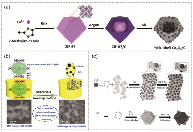
图12 (a) ZIF-67衍生的多级卵黄壳Co3O4/C十二面体示意图以及将ZIF-67在氩气气氛中450 ℃加热2 h,得到ZIF-67/C,然后将样品在270 ℃空气中退火3 h,得到蛋黄壳Co3O4/C[116];(b) 合成TiO2/C复合材料的示意图,其亚微米片剂形态源自MOF前体MIL125(Ti)[118];(c)用于合成CoSx-rGO-CoSx和rGO@CoSx复合材料的示意图[119]Fig. 12 (a) Schematic of ZIF-67-derived hierarchical yolk-shell Co3O4/C dodecahedrons. ZIF-67 was heated at 450 ℃ for 2 h in an argon atmosphere to obtain ZIF-67/C, and then the sample was annealed at 270 ℃ for 3 h in air to obtain yolk-shell Co3O4/C[116]. Copyright 2017, Tsinghua University Press and Springer-Verlag Berlin Heidelberg. (b) Schematic illustration for the synthesis of TiO2/C composite with submicron-tablets morphology derived from a MOF precursor, MIL125(Ti)[118]. Copyright 2015 Royal Society of Chemistry. (c) Schematic illustration of the procedures used to synthesize CoSx-rGO-CoSx and rGO@CoSx composites[119]. Copyright 2016 WILEY-VCH Verlag GmbH & Co. KGaA,Weinheim |
3.3.2 多元金属化合物
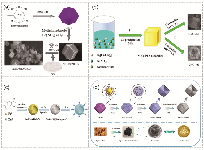
图13 (a) rGO/ZnO/Co3O4合成的简化示意图[124];(b) CNC-350和CNC-400制备[125];(c)中空Fe-Zn-S@S-doped-C微球的制备过程和锂离子存储特性示意图[127];(d) 阴极NMCS和阳极TPC制备离子工艺示意图[130]Fig. 13 (a) Simplified schematic diagram of rGO/ZnO/Co3O4 synthesis[124]. Copyright 2023, American Chemical Society. (b) Preparation process of CNC-350 and CNC-400[125]. Copyright 2023 The Authors. Published by American Chemical Society. (c) Schematic illustration of the preparation process and Li-ion storage properties of hollow Fe-Zn-S@S-doped-C microsphere[127]. Copyright 2019 Elsevier B.V. All rights reserved. (d) Schematic of cathode NMCS and anode TPC preparation process[130]. Copyright 2023 Elsevier B.V. All rights reserved. |