


1 引言
2 高电压静电纺丝技术概述
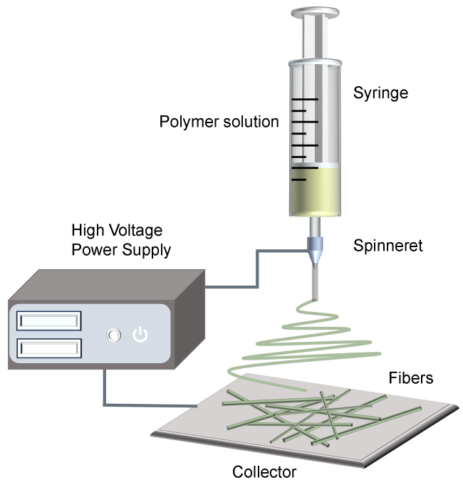
2.1 工作原理
2.2 参数选择
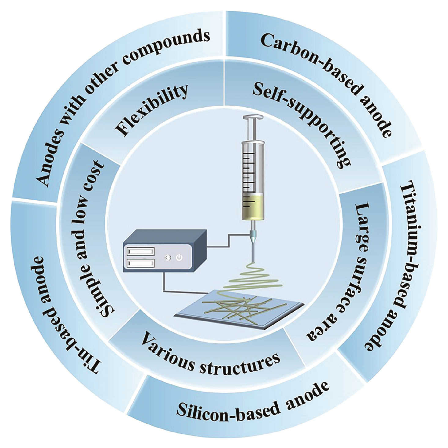
2.3 静电纺丝制备负极材料的优点
3 锂离子电池关键负极材料
3.1 碳基负极材料


3.2 钛基负极材料
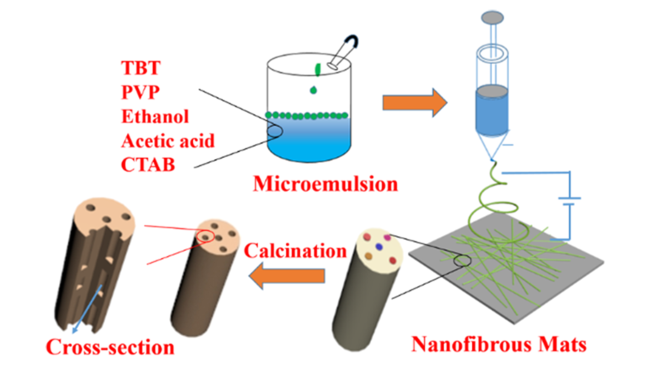
表1 电纺钛基负极材料用于锂离子电池及其电化学性能Table 1 Electrochemical performance of electrospun titanium-based nanofiber anodes for LIBs. |
| Material | Structure | Retention capacity(mAh·g-1)/ Cycles/Current rate(A·g-1) | Specific capacity(mAh·g-1)/ Current rate(A·g-1) | Ref |
|---|---|---|---|---|
| TiO2 | Porous nanofibers | 264.56/100/0.04 | 142.55/0.16 | 38 |
| TiO2 @C/N | Nanofibers | 388/400/0.3 | 310/1.5 | 41 |
| Ta-doped TiO2/C | Nanofibers | 399.3/1000/2 | 315.2/2 | 42 |
| TiO2 | Nanofibers | 139.4/100/0.067 | 45/0.67 | 39* |
| TiO2 | Hollow nanofibers | 144.7/100/0.067 | 60/0.67 | 39* |
| TiO2 with TiOxNy and TiN | Hollow nanofibers | 156/100/0.067 | 85/0.67 | 39* |
| Li4Ti5O12 | Porous nanofibers | 165.3/100/0.0175 | 149.1/1.75 | 49* |
| Li4Ti5O12 with TiOxNy and TiN | Nanofibers | 159.9/100/0.035 | 120/1.75 | 50* |
| Li4Ti5O12 with PANI | Nanofibers | 169.2/30/0.0175 | 137.1/1.75 | 51* |
| Li4Ti5O12 | Nanofibers | 158.9/30/0.0175 | 104.3/1.75 | 51* |
* 文献以倍率C为单位,为便于性能比较统一换算为以电流密度A·g-1为单位(TiO2基负极材料:1 C=0.335 A·g-1,Li4Ti5O12基负极材料:1 C=0.175 A·g-1) |
3.3 硅基负极材料

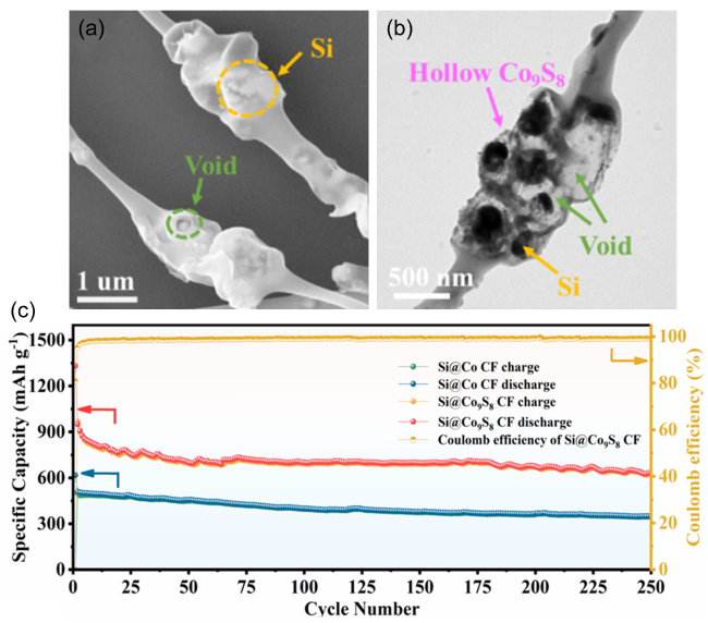
表2 电纺硅基负极材料用于锂离子电池及其电化学性能Table 2 Electrochemical performance of electrospun silicon-based nanofiber anodes for LIBs. |
| Material | Electrospinning solution(precursor/polymer/solvent) | Structure | Retention capacity(mAh·g-1)/Cycles/Current rate(A·g-1) | Specific capacity(mAh·g-1)/ Current rate(A·g-1) | Ref | |
|---|---|---|---|---|---|---|
| Si/CNF | Si -F127/PAN/DMF | Porous nanofiber | 870/100/0.1 | 405/5 | 59 | |
| Si/CNF | Si/PAN/DMF | Nanofiber | 172/100/0.1 | 111/1 | 59 | |
| Si@N-CNF | Si -Urea -PEG/PAN-PVB/DMF | Nanofiber | 689.7/150/0.2 | 768.4/1 640.8/2 | 60 | |
| Si@N-CNF | Si-Urea/PAN-PVB/DMF | Nanofiber | —— | 696.5/1, 559.5/2 | 60 | |
| Si/C-ZIF-8/CNFs | Si-ZIF-8/PAN/DMF | Pumpkin-like structure | 945.5/150/0.2 538.6/500/0.5 | 840.3/1, 672.5/2 | 62 | |
| Si-Ni-C | Si-Ni(CH3COO)24·H2O/PAN-PVP/DMF | Hollow structure | 622/100/0/1 524/100/0.2 | 400/1 300/2 | 63 | |
| Si@Co9S8 CF | Si@ZIF-67/PAN/DMF | Yolk shell structure | 1124/150/0.1 633.6/250/1 | 864/1 752/2 | 64 | |
3.4 锡基负极材料
表3 电纺锡基负极材料用于锂离子电池及其电化学性能Table 3 Electrochemical performance of electrospun tin-based nanofiber anodes for LIBs. |
| Material | Electrospinning solution (precursor/polymer/solvent) | Structure | Retention capacity(mAh·g-1)/ Cycles/Current rate(A·g-1) | Specific capacity(mAh·g-1)/ Current rate(A·g-1) | Ref |
|---|---|---|---|---|---|
| Sn-C | Tinoctoate/PAN and PMMA/DMF | Porous multichannel carbon microtubes | 648/140/0.1 | 570/0.4 295/2 | 75 |
| Sn@C@CNF | Sn-MOF/PAN/DMF | Hierarchical porous structure | 610.8/180/0.2 | 448.2/1 305.1/2 | 77 |
| MnO-Sn@CNF | MnSn(OH)6/PAN/DMF | Carbon fiber confining MnO-Sn nanocubes | 754/1000/1 | 800/1 447/5 | 78 |
| N-doped C@SnO2 | PAN/DMF+hydrothermal synthesis | SnO2 nanoflowers grow on the surface of NC Nanofibers | 750/100/1 | 763/1 684/2 | 83 |
| SnSe/C | SnCl2·2H2O and Se/PVP/DMF | Nanofibers | 405/500/1 | 429/3 384/4 | 90 |
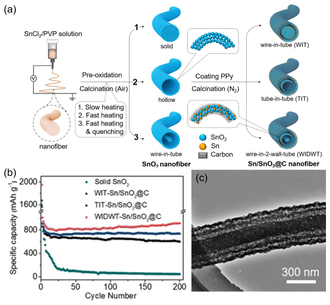
图8 (a)多壁Sn/SnO2@C中空纳米纤维制备流程图;(b)多壁Sn/SnO2@C中空纳米纤维在1.0 A·g-1电流密度下的循环性能曲线;(c)多壁Sn/SnO2@C中空纳米纤维的TEM 图[85]Fig. 8 (a)The fabrication scheme of multi-wall Sn/SnO2@C hollow nanofibers;(b)Cycling performances at a current density of 1.0 A·g-1 of multi-wall Sn/SnO2@C hollow nanofibers;(c)TEM image of multi-wall Sn/SnO2@C hollow nanofibers [85]. Copyright 2020, John Wiley and Sons |
3.5 其他金属化合物负极材料
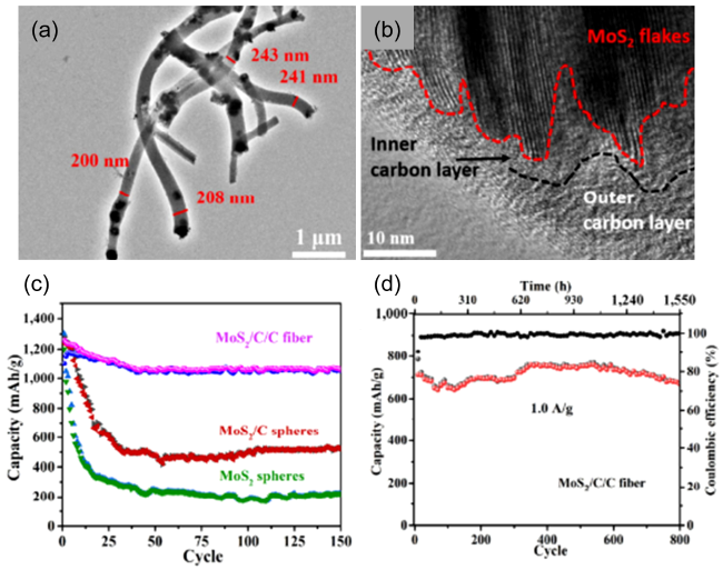
图9 (a)MoS2/C/C的TEM图;(b)MoS2/C/C的HRTEM图;(c)MoS2、MoS2/C、MoS2/C/C在0.2 A·g-1下的循环性能图;(d)MoS2/C/C在1.0 A·g-1下的长循环性能图[95]Fig. 9 (a)TEM image of MoS2/C/C;(b)HRTEM image of MoS2/C/C;(c)Cycling performances at a current density of 0.2 A·g-1 of the MoS2,MoS2/C,and MoS2/C/C fiber electrodes;(d)Long-time cycling performances at a current density of 1.0 A·g-1 of the MoS2/C/C fiber electrodes[95]. Copyright 2018, Springer Nature |

图10 (a)中空NiO纳米纤维的制备流程图;(b)中空NiO纳米纤维在2.0 A·g-1电流密度下的循环循环性能曲线[101]Fig. 10 (a)Schematic of the formation mechanism of the hollow NiO nanofibers using camphene via the facile two-step strategy;(b)Cycling performances at a current density of 2.0 A·g-1 of the hollow NiO nanofibers[101]. Copyright 2019, Elsevier |
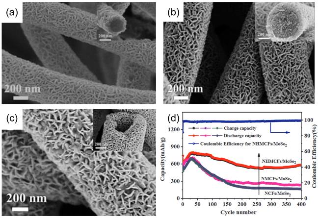
图11 (a)NCFs/MoSe2的SEM图;(b)NMCFs/MoSe2的SEM图;(c)NHMCFs/MoSe2的SEM图;(d)NCFs/MoSe2、NMCFs/MoSe2、NHMCFs/MoSe2在1.0 A·g-1电流密度下的循环性能图[104]Fig. 11 (a)SEM images of NCFs/MoSe2; (b)SEM images of NMCFs/MoSe2; (c)SEM images of NHMCFs/MoSe2; (d)Cycling performances at a current density of 1.0 A·g-1 of NCFs/ MoSe2,NMCFs/MoSe2, and NHMCFs/MoSe2[104]. Copyright 2021, Elsevier |