


1 引言
2 Fe-N-C催化剂的合成方法
2.1 空间限制法
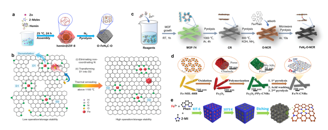
图1 Fe-N-C催化剂的合成方法:(a)一步热解法合成O-FeN4C-O示意图[30];(b)提高热解Fe-N-C催化剂的ORR稳定性的高温下微观结构演变示意图[31];(c)在不同的温度和气氛下通过三步热解法合成多孔FeN4-O-NCR催化剂示意图[34];(d)以一维Fe2O3为模板合成多孔碳纳米棒Fe/N-CNR催化剂示意图[39];(e)合成Fe-N-C/N-OMC催化剂的示意图[40]Fig. 1 Synthesis methods of Fe-N-C catalysts(a)Schematic diagram of synthesis process of O-FeN4C-O[30]. Copyright 2022 Elsevier Inc.(b)Schematic illustration of microstructure evolution at high temperatures for improving ORR stability of pyrolyzed Fe-N-C catalysts[31]. Copyright 2022 Wiley-VCH.(c)Synthesis of porous FeN4-O-NCR catalysts by three-step pyrolysis under different temperatures and atmospheres[34]. Copyright 2022 Wiley-VCH Gmbh.(d)Synthesis of porous carbon nanorod Fe/N-CNR catalysts using one-dimensional Fe2O3 as a template[39]. Copyright 2020 Elsevier B.V.(e)Schematic illustration for the synthesis of Fe-N-C/N-OMC catalyst[40]. Copyright 2020 Wiley-VCH Gmbh. |
2.2 模板法
表1 近年代表性Fe-N-C催化剂半电池和全电池测试性能Table 1 Summary of representative Fe-N-C catalysts half-cell and full-cell performance in recent years |
| Catalysts | Half-cell test | Performance | Single-cell test | Performance |
|---|---|---|---|---|
| FeNC-1200[31] | 10 000 square cycles between 0.6 and 1.0 V/RHE in O2-saturated 0.1 M HClO4 | ∆E1/2 8 mV | constant voltage of 0.5 V under H2-O2 condition for 30 h | current density loss 20% |
| Fe-AC-CVD[32] | 10 000 square cycles between 0.6 and 1.0 V/RHE in O2-saturated 0.5 M H2SO4 | ∆E1/2 17 mV | 30,000 square cycles between 0.6 and OCV in H2-Air PEMFC | current density loss 13% |
| O-FeN4-O[30] | 10 000 square cycles between 0.6 and 1.0 V/RHE in O2-saturated 0.5 M H2SO4 | ∆E1/2 10 mV | constant current density of 0.5 A·cm-2 under H2-O2 condition for 50 h | potential loss 33% |
| Fe-N-C/Pd[41] | 30 000 square cycles between 0.6 and 1.0 V/RHE in O2-saturated 0.1 M HClO4 | ∆E1/2 13.5 mV | - | - |
| ZIF-NC-0.5Fe-700[42] | 30 000 square cycles between 0.6 and 1.0 V/RHE in O2-saturated 0.5 M H2SO4 | ∆E1/2 31 mV | - | - |
| Fe-N-C/F[43] | - | - | constant voltage of 0.6 V under H2-O2 condition for 100 h | current density loss 3% |
| Fe/PI-1000-III-NH3[44] | - | - | constant current of 30mA under H2-O2 condition for 1000 h | potential loss 15% |
| PANI-FeCo-C[45] | - | - | constant voltage of 0.4 V under H2-O2 condition for 700 h | current density loss 3% |
| Fe-ZIF/CNT/1[46] | 1 000 square cycles between 0.9 and 1.4 V/RHE in N2-saturated 0.1 M HClO4 | ∆E1/2 42 mV | constant voltage of 0.4 V under H2-O2 condition for 30 h | current density loss 34% |
| Fe/N,S-HC[47] | 1 000 square cycles between 0.6 and 1.0 V/RHE in N2-saturated 0.1 M KOH | ∆E1/2 7 mV | - | - |
| Fe@MNC-OAc[35] | 10 000 square cycles between 0.6 and 1.0 V/RHE in O2-saturated 0.1 M HClO4 | ∆E1/2 9 mV | - | - |
| FeSA/FeAC-2DNPC[48] | 10 000 square cycles between 0.6 and 1.0 V/RHE in O2-saturated 0.5 M H2SO4 | ∆E1/2 15 mV | constant voltage of 0.5 V under H2-Air condition for 30 h | slight decrease in current density for the first 32 hours, then stabilized |
| P(AA-MA)(5-1)-Fe-N[49] | 5 000 square cycles between 0.6 and 1.0 V/RHE in O2-saturated 0.5 M H2SO4 | ∆E1/2 5 mV | constant voltage of 0.55 V under H2-O2 condition for 30 h | virtually no loss of current density during the initial 37 hours |
2.3 其他方法
3 Fe-N-C催化剂稳定性测试标准
3.1 半电池测试
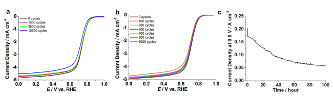
图2 在RRDE和MEA稳定性测试中测量的FeIM/ZIF-8的ORR极化曲线:RRDE测试条件包括在(a)0.1 M Ar饱和的HClO4或(b) 0.1 M O2饱和的HClO4中以50 mV·s-1的速度从0.0到1.1V循环多次,然后在O2饱和的HClO4中以10 mV·s-1的扫描速率测量极化曲线; (c)在H2-Air中进行100 h稳定性测试,测量以FeIM/ZIF-8为阴极催化剂的单体电池(Nafion 117膜)在0.5 V时的电流密度[55]Fig. 2 ORR polarization curves of FeIM/ZIF-8 measured during RRDE and MEA stability test: RRDE test conditions include cycling from 0.0 to 1.1 V at 50 mV·s-1 in(a)0.1 M Ar-purged HClO4 or(b)0.1 M O2-purged HClO4 at 25 ℃ for multiple cycles, followed by polarization curve measurement in O2-purged HClO4 at the scan rate of 10 mV·s-1.(c) 100-hour stability test by measuring the current density at 0.5 V of a single cell with FeIM/ZIF-8 as the cathode catalyst(Nafion 117 membrane)operated with H2-air[55]. Copyright 2012 The Royal Society of Chemistry. |
3.2 单电池测试
3.3 两种测试结果的差异性分析
4 Fe-N-C催化剂的失活机制
4.1 脱金属
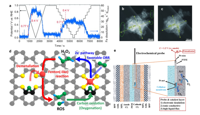
图4 (a)计时电流法实验中SFC/ICP-MS记录的铁的溶解情况,实验温度和步长分别为20 ℃和0.1 V[61]; 在0.1M HClO4中进行5000次电压循环(1.2~1.5V)前(b)后(c)拍摄的单个Fe-N-C颗粒暗场IL-STEM显微照片[61];(d)描述Fe-N-C催化剂失活机制相互耦合循环的示意图,包括脱金属、Fenton反应和碳氧化[67];(e)电化学探针法检测工况条件下催化层H2O2浓度的示意图[64]Fig. 4 Deactivation mechanism of Fe-N-C catalysts:(a)Online SFC/ICP-MS results. The Fe dissolution was recorded at 20 ℃ during a stepwise chronoamperometry experiment with a 0.1 V step size[61]; Morphology change of a single Fe-N-C particle. Dark-field IL-STEM micrographs b)before and c) after 5000 cycles performed between 1.2 and 1.5 V at 50 ℃ in a 0.1 M HClO4 electrolyte[61]. Copyright 2015 WILEY-VCH Verlag GmbH & Co.KGaA, Weinheim.(d) Schematic illustration describing autocatalytic degradation cycle comprising demetalation, Fenton(-like) reaction, and carbon oxidation[67]. Copyright 2021 Elsevier Inc.(e)Schematic of the electrochemical probe method to in-operando monitor the H2O2 concentration in the fuel cell catalyst layer[64]. Copyright 2022 Elsevier B.V. |
4.2 碳氧化腐蚀
4.3 质子化
4.4 微孔水淹
5 Fe-N-C催化剂的延寿策略
5.1 稳定的碳载体
5.1.1 提高石墨化度
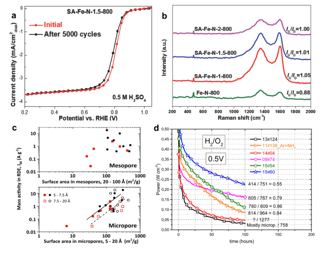
图5 构建稳定碳载体的策略:(a)SA-Fe-N-1.5-800的AST测试结果[74];(b)使用不同浓度的SA合成的SA-Fe-N催化剂与不含SA的Fe-N-C催化剂的拉曼光谱结果[74];(c)微孔/介孔面积与ORR质量活性关系[76];(d)六种含不同微孔率的Fe-N-C催化剂的稳定性测试结果[77]Fig. 5 Strategies for building stable carbon substrate:(a)AST test results of SA-Fe-N-1.5-800[74];(b)Raman spectra of SA-Fe-N catalysts synthesized using different concentrations of SA versus Fe-N-C catalysts without SA[74]. Copyright 2018 WILEY-VCH Verlag GmbH & Co.KGaA, Weinheim.(c)Relationship between mesopore and micropore area and ORR mass activity[76]. Copyright 2021 Elsevier Inc.(d)Stability test results of six Fe-N-C catalysts with different micropore ratios[77]. Copyright 2016 American Chemistry Society |
5.1.2 调节分级孔占比
5.2 稳定的活性位点
5.2.1 调控活性位点结构
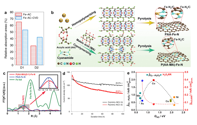
图6 构建稳定活性位点的策略:(a)CVD处理前后Fe-N-C催化剂中D1和D2位点含量的比较[32];(b)PAA-Fe-N和P(AA-MA)-Fe-N催化剂合成示意图,分别由低结合常数的PAA-Fe和高结合常数的P(AA-MA)-Fe作为前驱体制备[49];(c)P(AA-MA)(5-1)-Fe-N、PAA-Fe-N和铁箔样品的k3加权FT-EXAFS光谱[49];(d)Co(mIm)-NC(1.0)和Fe(mIm)-NC(1.0)催化剂在MEA中以0.7 V的恒定电压持续100 h的耐久性测试结果[82];(e)原子分散的M-N-C催化剂(M=Mn、Fe、Co、Ni和Cu)的电化学合成H2O2和H2O2还原趋势[83]Fig. 6 Strategies for constructing stable active sites:(a)Comparison of D1 and D2 sites contents in Fe-N-C catalysts before and after CVD treatment[32]. Copyright 2022 Springer Nature Limited.(b)PAA-Fe-N and P(AA-MA)-Fe-N catalysts were prepared by lower binding constant PAA-Fe and higher binding constant P(AA-MA)-Fe as precursor, respectively[49];(c)k3-weighted FT-EXAFS spectra of P(AA-MA)(5-1)-Fe-N, PAA-Fe-N, and Fe foil samples[49]. Copyright 2021 Wiley-VCH Gmbh.(d)Durability tests of the Co(mIm)-NC(1.0)and Fe(mIm)-NC(1.0)catalysts in MEA in 1 bar H2-air at a constant cell voltage of 0.7 V for 100 h[82]. Copyright 2020 Springer Nature.(e)The trends in electrochemical H2O2 production and H2O2 reduction over a series of M-N-C materials(M=Mn, Fe, Co, Ni, and Cu)exclusively comprising atomically dispersed M-Nx sites from molecular first-principles to bench-scale electrolyzers operating at industrial current density[83]. Copyright 2019 American Chemistry Society. |
5.2.2 使用不含铁的M-N-C催化剂
5.3 避免发生Fenton反应
5.3.1 降低铁/铁氧化物颗粒含量
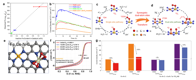
图7 避免发生芬顿反应的策略:(a)20圈快速循环稳定性测试结果:铁的溶解量与催化剂中结晶铁含量之间呈现正相关[87];(b)在0.5 V下进行50 h的恒电压耐久性测试时,电流密度与时间的关系曲线[87];Pt AMS(c)和Pt = N2 = Fe ABA(d)的ORR机制示意图[88];(e)Fe,Ce-N-C的结构示意图[92];(f)在O2饱和的0.1 M HClO4中进行30 000次电压循环(0.6~1.0V)的实验结果[92];(g)经过加速耐久性测试后,是否加入自由基清除剂Ta-TiOx/KB的PEMFC的电流密度衰减情况比较[93]Fig. 7 Strategies to avoid Fenton reaction:(a)Positive correlation between the cumulative amounts of Fe dissolved during the 20 fast cycles and the total content of crystalline Fe structures in the catalysts[87];(b)Current density versus time during the durability test for 50 h at 0.5 V[87]. Copyright 2016 American Chemistry Society. Schematic of the ORR mechanism for Pt AMS(c)and Pt = N2 = Fe ABA(d)[88]. Copyright 2022 Springer Nature.(e)The optimized structure of Fe,Ce-N-C[92];(f)accelerated degradation test(ADT)by cycling the potential(0.6~1.0 V)in O2-saturated 0.1 M HClO4 for 30 000 cycles to study the stability of the best-performing Fe,Ce-N-C[92]. Copyright 2023 Elsevier Inc.(g) Current density decay comparison for cells with and without Ta-TiOx/KB after the ADT[92]. Copyright 2022 Springer Nature Limited. |