


1 引言
2 气体分子间的催化反应


图2 团簇结构模型: (a) 在无缺陷SiO2表面的两配位桥氧≡Si—O—Si≡结构;(a’) 金属原子(Cu, Pd, Cs)吸附在桥氧上的结构;(b) SiO2表面的E’S中心≡Si·结构;(b’) 一个金属原子(Cu, Pd, Cs)吸附在E’S中心上,≡Si—M结构;(c) 一个四面体T原子的非桥氧中心(NBO)≡Si—O·结构;(c’) 一个金属原子(Cu, Pd, Cs)吸附在NBO上的结构;(d) 两个四面体T原子的非桥氧中心(NBO)≡Si—O·结构;(d’) 一个Cu或Pd金属原子吸附在NBO上的结构;(d”) 一个Cs金属原子吸附在NBO上的结构;(e) 中性氧缺陷中心≡Si—Si≡结构;(e’) 一个Cu或Pd金属原子吸附在中性氧缺陷中心≡Si—M—Si≡上的结构[6]Fig.2 Cluster models of (a) a two-coordinated bridging oxygen, ≡Si—O—Si≡, at the non-defective silica surface; (a’) a metal atom (Cu, Pd, Cs) adsorbed on-top of the bridging oxygen; (b) a E’S center, ≡Si·, at the silica surface and (b’) a metal atom (Cu, Pd, Cs) adsorbed on the E’S center, ≡Si—M; (c) One-tetrahedron, 1-T, cluster models of a nonbridging oxygen (NBO) center, ≡Si—O·, at the silica surface and (c’) a metal atom (Cu, Pd, Cs) adsorbed on the NBO center; (d) two-tetrahedra, 2-T, cluster models of a nonbridging oxygen (NBO) defect center,≡Si—O·, at the silica surface, (d’) a Cu or Pd atom adsorbed on the NBO center and (d”) a Cs atom adsorbed on a NBO center; (e) a neutral oxygen vacancy center, ≡Si—Si≡, at the silica surface, and (e’) a Cu or Pd atom adsorbed on the neutral oxygen vacancy, ≡Si—M—Si≡[6] |
表1 Pt/SiO2催化剂的物理性质和CO吸附量[8]Table 1 Physical properties and CO adsorption values of Pt/SiO2 catalysts[8] |
| Catalyst | Surface area/m2·g-1 | Average particle sizea/nm | Mass ratio of Pt:Si | CO adsorptionc/mmol·g-1 |
|---|---|---|---|---|
| SiO2 | 325 | - | - | |
| Pt/SiO2-773 K H2 | 340 | 2.4±1.2 | 3.5/96.5 | 54.9 |
| Pt/SiO2-1073 K H2 | 320 | 2.2±0.9 | 3.9/96.1 | 40.3 |
| Pt/SiO2-1273 K H2 | 217 | 3.2±1.1 | 4.1/95.9 | n.d. |
a As determined from >200 particles in TEM images.b As determined by XRF.c As determined by CO-pulse measurements. |
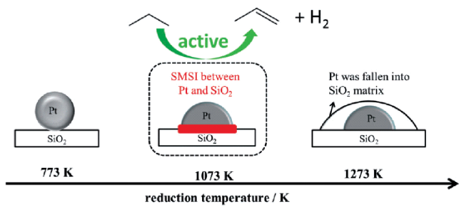
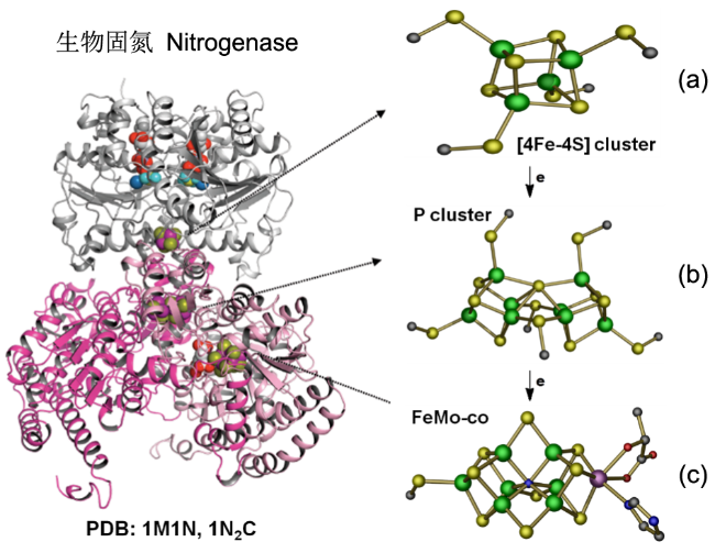
图8 固氮酶的晶体结构(图左)及催化过程中参与电子传递的组分的相对位置(图右)。[4Fe-4S]团簇、P团簇和FeMo-co的位置如箭头所示(PDB蛋白数据库中的1M1N和1N2C条目),(a) Fe蛋白;(b) P簇;(c) FeMo辅酶。绿球:Fe;黄球:S;紫球:Mo;红球:O;暗蓝球:NFig.8 X-ray crystal structure of half of the ADP·AlF4-stabilized Fe protein/MoFe protein complex (left) and the relative positions of components that are involved in the electron flow during catalysis (right). The positions of [4Fe4S] cluster, P-cluster, and FeMo-co are indicated. The atoms colored as follows: Fe, green; S, yellow; Mo, purple; O, red; N, dark blue; (PDB entries 1M1N and 1N2C) |

3 极端条件(高压)下气体分子间的凝聚态反应

图10 H2的实验/理论压力-温度相图[27]。两种形成金属氢(MH)的途径:I是低温途径,II是高温途径。途径I中,LP表示绝缘性的仲氢相;随着在超低温下压力(GPa)的增大,相I中的H2分子形成了轻微扭曲的六方堆积(P21/c)的相II,150 GPa以上形成的相III和IV,晶体结构仍然接近于六方最密堆积(hcp),只是随压力的增大,晶胞收缩与密度升高加剧,直至最后固态金属氢的形成。氢分子解离成氢原子,成键电子在超高压下成为具化学活性的自由电子。另外,等离子相变指向液态金属原子氢的转变Fig.10 Experimental/theoretical P-T phase diagram of hydrogen. Shown are two pathways to MH: I is the low-temperature pathway, and II is the high-temperature pathway. In pathway I, phases for pure para hydrogen have lettered names: LP, low pressure; BSP, broken symmetry phase; and H-A, hydrogen-A. The plasma phase transition is the transition to liquid metallic atomic hydrogen[27] |

图11 在83 GPa下生成的稳定的Xe2O5 (a)和Xe3O2 (b)结构[33]。Xe原子蓝色,O原子红色,O原子为-2氧化态,较深的红色表示1个O原子只与1个Xe原子结合,Xe原子的氧化态由不同深浅的蓝色表示。最浅的蓝色表示氧化态为0,中等蓝色表示+4,最深的蓝色表示+6。Xe2O5和Xe3O2中的Xe原子在每个结构中以两种不同的氧化态存在,Xe2O5中为+4和+6,Xe3O2为0和+4Fig.11 Structures of the stable xenon oxides at 83 GPa. Xe2O5 (a) and Xe3O2 (b)[33]. Xenon atoms are shown in blue shades and oxygen atoms in red shades. The oxygen atoms have an oxidation state of -2, and the darker shade of red indicates an oxygen atom that bonds only to one xenon atom. The oxidation states of the xenon atoms are indicated by different shades of blue. The lightest blue indicates an oxidation state of 0, the medium shade one of +4 and the darkest blue one of +6. The xenon atoms in Xe2O5 and Xe3O2 exist in two different oxidation states within each structure, +4 and +6 in Xe2O5 and 0 and +4 in Xe3O2 |

图12 氙氧化物的凸包(Convex-hull)相图[33]。对于一个化学计量学XemOn的结构,每个原子的形成焓由ΔHf(XemOn) = (H(XemOn) - (mH(Xe) + nH(O)))/(m+n)得出,H是每个单元在相关压力下的焓。所示的3个凸包分别为83GPa(绿色)、150GPa(红色)和200GPa(蓝色)。每个彩色圆圈表示一个结构,该结构在分解时是稳定的,连接稳定结构焓的彩色线表示凸包Fig.12 Convex-hull diagram for xenon oxides that shows the calculated enthalpies of formation per atom from the elements for the predicted stable phases[33]. For a structure of stoichiometry XemOn, the enthalpy of formation per atom is given by ΔHf(XemOn) = (H(XemOn) - (mH(Xe) + nH(O)))/(m+n), where H is the enthalpy of each formula unit under the relevant pressure. The three convex hulls shown are for 83 GPa (green), 150 GPa (red) and 200 GPa (blue). Each coloured circle denotes a structure that is stable against decomposition. The coloured lines that join the enthalpies of the stable structures denote the convex hull |
