


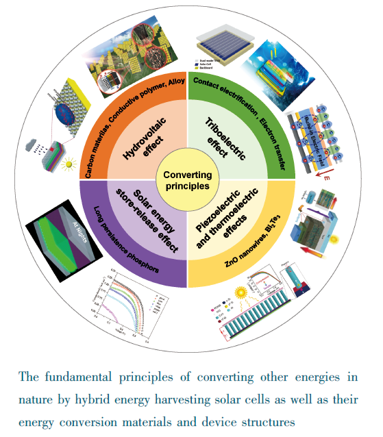
1 引言
2 转换雨滴水动能的混合能量采集太阳能电池
2.1 水伏效应
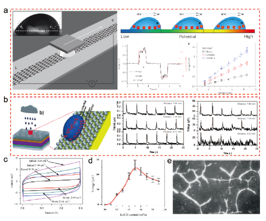
图1 (a) 0.6 mol/L的NaCl液滴在单层石墨烯表面滑动产生水伏电势的器件结构、原理及电学输出[20]。(b) 通过水伏效应与光伏效应耦合构建的混合能量采集太阳能电池器件与电流、电压输出[39]。(c) 模拟雨滴在石墨烯表面铺展/收缩过程中测试的循环伏安曲线[40]。(d) 在测定雨滴与G-CB/PTFE复合电极时,输出电压随G-CB含量的变化[41]。(e) 利用偏光显微镜观察的绢云母在复合材料中的分布[41]Fig.1 (a) The device structure, principle and electric outputs of moving a 0.6 mol/L NaCl aqueous droplet on monolayer graphene to create hydrovoltaic potentials[20]. (b) The structure and current and voltage outputs of hybrid energy harvesting solar cell by coupling hydrovoltaic and photovoltaic effects[39]. (c) The CV curves for symmetric dummy cells from graphene film /raindrop[40]. (d) Voltage data created by dropping simulated raindrops on G-CB/PTFE electrode[41]. (e) The polarizing microscopic image of sericite in its composite[41] |
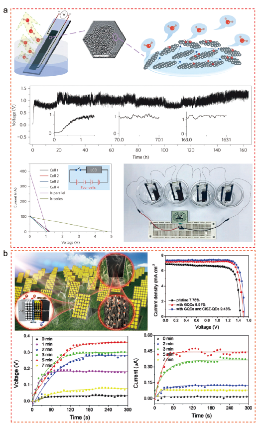
图2 (a) 水蒸气在碳黑薄膜孔道流动产生流动电势的装置结构以及单结和四结电池的电压输出[46]。(b) 可同时转换太阳能和蒸发能的碳基全无机CsPbBr3钙钛矿太阳能电池的J-V曲线及受水蒸气刺激产生的电流、电压输出[47]Fig.2 (a) The set-up for measuring evaporation-induced voltage as well as the voltage outputs of single- and multi-junction cells[46]. (b) J-V curves for the carbon-based all-inorganic CsPbBr3 perovskite solar cell as well as current and voltage outputs induced by water-vapor[47] |
2.2 摩擦电效应

图3 (a) 液-固型TENG/硅太阳能电池叠层器件结构及其在标准太阳光照和模拟降雨的输出性能[48]。(b) 液-固和固-固耦合型TENG/硅太阳能电池叠层器件结构[49]。(c) 基于褶皱PDMS薄膜的TENG/硅太阳能电池结构与J-V曲线[50]Fig.3 (a) The structure of liquid-solid TENG/Si solar cell device and the performances under standard sunlight irradiation or simulated raining conditions[48]. (b) The device structure of coupling liquid-solid and solid-solid TENG/Si solar cell tandem[49]. (c) J-V curves based on nano-wrinkled PDMS TENG/Si solar cell[50] |
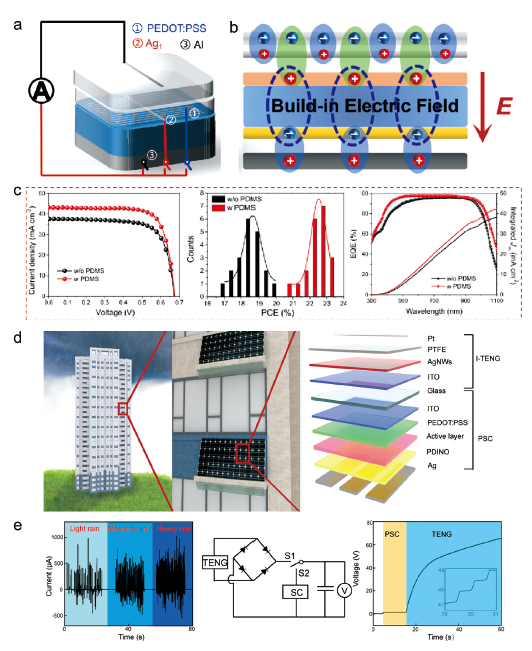
图4 (a) 基于三电极液-固型TENG/单晶硅叠层的混合能量采集太阳能电池结构[52]。(b) 静电场增强光生内建电场机制[52]。(c) 光伏性能[52]。(d) 光伏建筑一体化示意图[53]。(e) 三种模拟降水密度下TENG的Isc,充电电路图以及混合系统对商用电容器充电过程的电压曲线[53]Fig.4 (a) The hybrid energy harvesting solar cell device based on three-electrode-typed liquid-solid TENG/Si tandem[52]. (b) The enhanced build-in electric field assisted by electrostatic field[52]. (c) The photovoltaic performances[52]. (d) Schematic illustration of BIPV[53]. (e) Isc of TENG under three different simulated precipitation densities; Diagram of the charging circuit and voltage curves of a commercial capacitor charging process by hybrid system[53] |
3 基于储光-发光效应的混合能量采集太阳能电池

图5 (a) 染料敏化太阳能电池在1个标准太阳光照和黑暗环境的J-V曲线[54]。(b) 基于长余辉材料的混合能量采集太阳能电池结构[54]。(c) N719-TiO2/LPP光阳极经光照1 min后的照片及其DSSC的效果图[54]。(d) N719-TiO2/LPP光阳极的PL激发谱[54]。(e) 混合能量采集太阳能电池在黑暗环境的J-V曲线[54]。(f) 基于储光-发光效应构建的双面DSSC器件结构以及(g) 工作原理[55]。(h) TiO2/LPP阳极的激发和发射光谱及其DSSC的J-V曲线[55]Fig.5 (a) The J-V curves of a traditional DSSC recorded under one standard sun and in the dark[54]. (b) The device structure of hybrid energy harvesting solar cell based on LPPs[54]. (c) Schematic diagrams of photoluminescence for N719-TiO2/LPP photoanodes and their hybrid energy harvesting solar cells at nights[54]. (d) The PL emission of N719-TiO2/LPP photoanodes[54]. (e) The J-V curves of hybrid energy harvesting solar cells recorded in the dark[54]. (f) The device structure and (g) working principle of a bifacial DSSC based on light storing-emitting effect[55]. (h) The excitation and emission spectra of the TiO2/LPP anode as well as J-V curves of their DSSCs[55] |
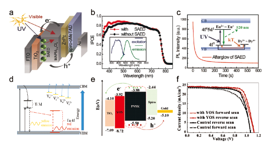
图6 (a) 基于SAED骨架层PSC器件结构图[56]。(b) SAED改性前后器件的IPCE图谱以及SAED层激发和发射光谱[56]。(c) SAED长余光发射光谱及发光机理[56]。(d) YOS发光机理[57]。(e) 基于YOS骨架层PSC器件能级排列示意图以及(f) J-V曲线[57]Fig.6 (a) Structure of SAED-based PSCs[56]. (b) The IPCE spectra of PSCs with and without SAED. The inset shows the excitation and emission spectra of the SAED film[56]. (c) Afterglow characteristics of SAED film, the insets show the phosphorescence mechanism[56]. (d) A schematic diagram of the afterglow mechanism of YOS[57]. (e) Band alignment and (f) J-V curves for hysteresis effect at forward and reverse scan of YOS-based mesoporous PSCs[57] |
4 基于压电、热电效应的混合能量采集太阳能电池
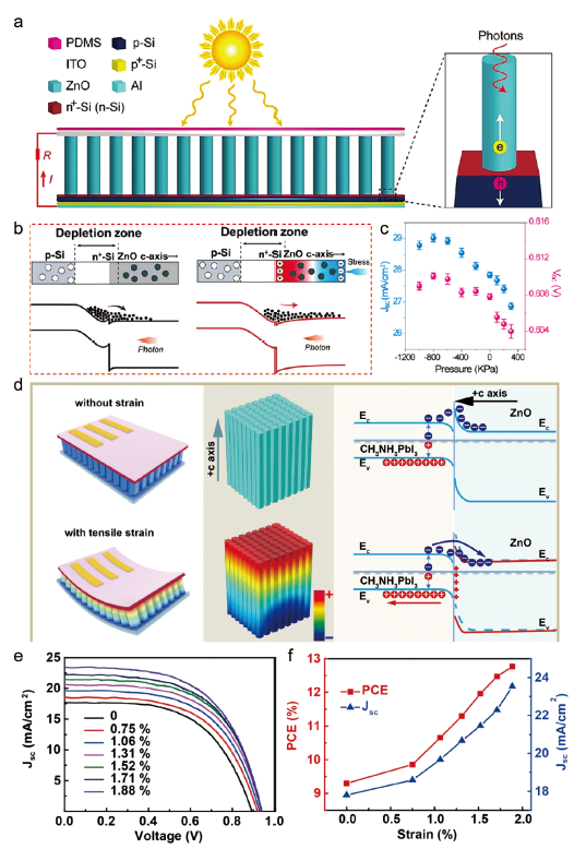
图7 (a) 基于压电光电子效应构建的硅基纳米异质结太阳能电池[60]。(b) 未施加压应力和施加压应力时p-n结的能带结构图[60]。(c) 太阳能电池在施加不同压应力时的J-V曲线[60]。(d) 柔性钙钛矿电池器件中压电光电子效应原理图和能带图[61]。(e) 连续静态压缩应变下器件的J-V曲线[61]。(f) 光电转换效率和短路电流密度在连续静态压缩应变下的依赖关系[61]Fig.7 (a) The device structure of a silicon heterojunction solar cell based on piezo-phototronic effect[60]. (b) The energy band diagrams for the p-n junction contacts with and without positive press[60]. (c) The J-V curves of the solar cell recorded under different presses[60]. (d) Schematics and energy-band diagrams demonstrating the piezo-phototronic effect on device[61]. (e) J-V curves of devices with continuous static tensile strains[61]. (f) Dependences of PCE and Jsc under continuous static tensile strains[61] |
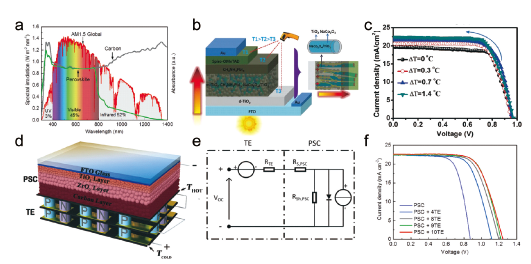
图8 (a) AM 1.5G太阳光谱[63]。(b) 基于NaCo2O4/TiO2纳米线的钙钛矿太阳能电池结构及电子在光阳极中的传输路径[62]。(c) 钙钛矿太阳能电池在不同温差时的J-V曲线[62]。(d) 杂化钙钛矿太阳能电池/热电叠层器件结构及(e) 等效电路图[63]。(f) 叠层不同数量热电器件时杂化电池的J-V曲线[63]Fig.8 (a) AM 1.5G solar spectrum[63]. (b) The perovskite solar cell structure based on NaCo2O4/TiO2 nanowires and electron transport route across photoanode[62]. (c) The J-V curves of the perovskite solar cell recorded at various temperature differences[62]. (d) The perovskite/thermoelectric hybrid device structure and (e) corresponding equivalent electric circuit diagram[63]. (f) J-V curves of the hybrid devices containing different numbers of thermoelectric modules under AM 1.5G sunlight[63] |