


1 引言

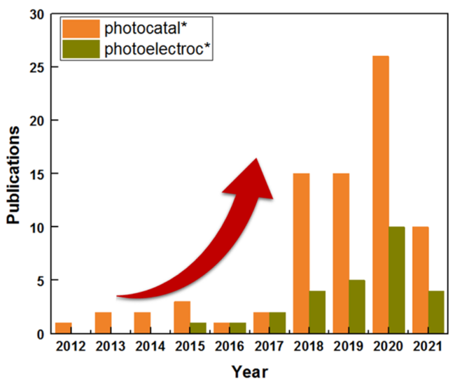
图1 2010—2021年涉及主题关键词“graphyne”或“graphdiyne”的年发表量和被引量(截至2021年5月2日,数据来自Web of Science数据库)Fig. 1 Number of yearly publications and citations from 2010 to 2021 involving the topic keywords “graphyne” or “graphdiyne.” Retrieved on May 2nd, 2021 from the Web of Science database |
2 石墨炔的合成与表征
2.1 二维石墨双炔薄膜的发现与合成
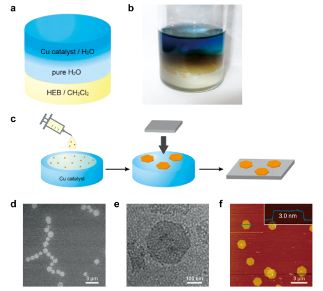
图5 液/液和气/液界面合成石墨双炔示意图及其显微形貌:液/液界面合成过程示意图(a)和照片(b);(c) 气/液界面合成及转移过程;(d) HMDS/Si(100) 的 SEM 图像;(e) 弹性碳网上的 TEM 图像;(f) HMDS/Si(100) 上的 AFM 形貌图及其沿蓝线的横截面分析[42]Fig. 5 Schematic illustration of liquid/liquid and gas/liquid interfacial synthetic procedure, and micrographs[42].(a) Schematic illustration and (b) photo of liquid/liquid interfacial synthetic procedure; (c) gas/liquid interfacial synthesis and transfer process; (d) SEM micrograph on HMDS/Si(100); (e) TEM micrograph on an elastic carbon grid; (f) AFM topographicimage on HMDS/Si(100) and its cross-sectional analysis along the blue line. Copyright 2017, American Chemical Society |
2.2 石墨双炔的形貌控制制备
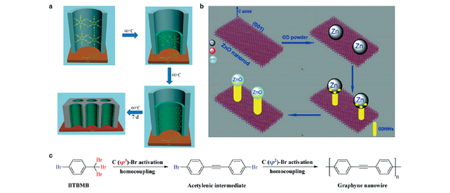
图6 一维结构石墨炔制备工艺:(a) GDNT 阵列的制备过程示意图[46];(b) VLS法制备GDNWs的过程示意图[50];(c) 分步脱卤均偶联反应制备石墨炔纳米线[53]Fig. 6 Preparation process of one-dimensional graphynes[46,50,53].(a) The process to fabricate GDNT arrays[46]; (b) Schematic illustration of the VLS process in the growth of GDNWs[50]; (c) The schematic illustration shows the stepwise dehalogenative homocoupling reactions, which results in the formation of a graphyne nanowire[53]. Copyright 2011, American Chemical Society; Copyright 2012, Royal Society of Chemistry; Copyright 2020, Royal Society of Chemistry |
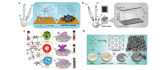
图7 三维石墨双炔的制备工艺[43,48,54,55]:(a) 在Cu基底上制备石墨双炔纳米墙结构的实验装置和示意图[54];(b) 通过铜箔包封催化在任意基底上制备 GDY 纳米壁的示意图[43];(c) “爆炸法”制备石墨双炔示意图[55];(d) 以硅藻土为模板制备 3DGDY的示意图[48]Fig. 7 Preparation processes of 3D graphdiynes[43,48,54,55].(a) Schematic illustration of the experimental setup for the synthesis of graphdiyne nanowalls on Cu substrate[54]; (b) Schematic illustration of GDY nanowalls on arbitrary substrates via copper envelope catalysis[43]; (c) Illustrations of the “explosion” preparation processes.[55]; (d) Schematic illustration of the experimental setup for the 3DGDY synthesis using diatomite as template[48]. Copyright 2015, American Chemical Society; Copyright 2017, Wiley-VCH; Copyright 2017, Royal Society of Chemistry; Copyright 2018, Wiley-VCH |
2.3 γ-石墨单炔及其衍生物的机械化学合成
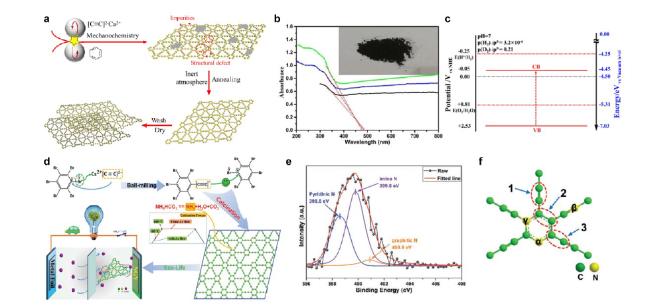
图8 γ-石墨单炔及氮掺杂石墨单炔的制备和表征[63,68]:(a)以苯为前驱体制备γ-石墨单炔的过程示意图,γ-石墨单炔的(b)紫外-可见漫反射吸收光谱(插图:样品照片)和(c)能带结构[63];氮掺杂γ-石墨单炔的(d)制备过程,(e) N 1s XPS光谱和(f)结构单元[68]Fig. 8 Preparation and characterization of γ-graphyne and nitrogen-doped graphyne[63,68].(a) Preparation of γ-graphyne using benzene as precursor; (b) UV-vis diffusion reflectance spectra (insert: the photo of sample), and (c) energy band of γ-graphyne[63]; (d) Preparation, (e) N 1s XPS spectra and (f) structural unit of nitrogen doped γ-graphyne[68]. Copyright 2018, Elsevier; Copyright 2020, Wiley-VCH |
2.4 石墨炔的表征方法与技术

图9 石墨炔形貌和晶体结构表征[40,54,64]:Cu基底上石墨双炔纳米壁的SEM图像:(a)俯视图,(b)横截面图;(c) Si/SiO2基底上剥离石墨双炔薄膜的 AFM 图像[54];γ-石墨单炔的(d~e) HRTEM图像和(f)SAED图[64];石墨双炔薄膜的(g)HRTEM图像,(h) SAED图和(i)XRD图[40]Fig. 9 Characterizations of morphology and crystal structures for graphynes[40,54,64].SEM images of graphdiyne nanowalls on Cu substrate: (a) top view, (b) cross-sectional view; (c) AFM image of an exfoliated sample on Si/SiO2 substrate[54]; (d~e) HRTEM image, and (f) SAED patterns of γ-graphyne[64]; (g) HRTEM image, (h) SAED patterns, and (i) XRD pattern of graphdiyne film[40]. Copyright 2015, American Chemical Society; Copyright 2019, Royal Society of Chemistry; Copyright 2010, Royal Society of Chemistry |
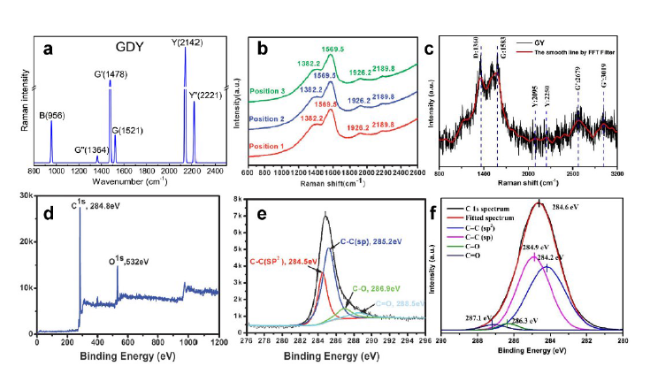
图10 石墨炔碳成键表征[40,63,80]:(a) 计算得到的石墨双炔拉曼光谱[80];石墨双炔薄膜的(b)拉曼光谱和(d,e)XPS光谱[40];γ-石墨单炔的(c)拉曼光谱和 (f) C1s XPS 光谱Fig. 10 Characterizations of chemical bonding of the carbon atoms for graphynes[40,63,80].(a) Calculated Raman spectra of GDY[80] ; (b) Raman spectra and (d,e) XPS spectra of graphdiyne film[40]; (c) Raman spectra and (f) C1s XPS spectra of γ-graphyne[63]. Copyright 2016, American Chemical Society; Copyright 2010, Royal Society of Chemistry; Copyright 2018, Elsevier |
3 石墨炔基光催化材料的制备与应用
表1 已报道的石墨炔基光催化剂的应用Table 1 Application of the reported GYs-based photocatalysts. |
| No. | Photocatalysts | Applications | Performances | Roles | ref |
|---|---|---|---|---|---|
| 1 | P25-GDY | MB degaradation | 4.5% increase than P25-graphene | e- acceptor | 82 |
| 2 | TiO2@β-GDY | MB degaradation | >TiO2@γ-GDY>TiO2 | e- acceptor | 83 |
| 3 | GDY-NTNS | RhB degaradation | 1.6 times faster than NTNS | e- pool | 84 |
| 4 | ZnO-GDY | MB degaradation | 2-fold higher than ZnO | e- acceptor | 85 |
| 5 | Ag3PO4@γ-GY | NFL/HNP/PH degaradation | 10~20 times higher than Ag3PO4 | e- transfer | 86 |
| 6 | Ag3PO4/GDY emulsion | MB degaradation; Water oxidation | >Ag3PO4/graphene>Ag3PO4/CNT> Ag3PO4 | e- acceptor; hole transfer mediator | 87 |
| 7 | TA-BGY | MO degaradation; E.coli inactivation | 99% (8h), 150 mW·cm-2 Xe 100% (1h), 100 mW·cm-2 Xe | Host | 88 |
| 8 | Ag/AgBr/GO/GDY | MO degaradation | >Ag/AgBr/GDY>Ag/AgBr/GO>Ag/AgBr | e- collector | 89 |
| 9 | TiO2 /GDY | RhB degaradation Antibacterial | - | e- transfer Biocompatibility | 90 |
| 10 | CdSe QDs/GDY | Photocathode | H2 : 90% ± 5% faradic efficiency | h+ transfer | 91 |
| 11 | GDY/BiVO4 | Photoanode | Iph two times BiVO4 | h+ extraction | 43 |
| 12 | Superhydrophilic CoAl-LDH/GDY /BiVO4 | Photoanode | 3.15 mA·cm-2 (1.23 V vs. RHE) | Interfacial mass/ e-transfer | 92 |
| 13 | g-C3N4/GDY | Photocathode | Iph 3-folds higher than g-C3N4 | h+ transfer | 93 |
| 14 | g-C3N4/GDY/NiFe-LDH | Photoanode | Iph 45-folds higher than g-C3N4 | h+ transport | 94 |
| 15 | GDYO/TiO2 | Photocathode | Iph 10-folds higher than TiO2 | Charge transfer | 95 |
| 16 | SiHJ/GDY/NiOx | Photoanode | Iph twice higher than SiHJ/NiOx | Conductivity; catalytic activity | 96 |
| 17 | PTEB | Photocathode | 10 μA·cm-2 (0.3 V vs RHE) | Host | 97 |
| 18 | Pyr-GDY | Photocathode | 12 times GDY | Host | 98 |
| 19 | γ-GY/TiO2 NT | Photoanode PEC degradation PEC NH3 synthesis | 1.3~6.5 folds higher than TiO2 | Heterojunction | 99 |
| 20 | Ag3PO4/GDY/g-C3N4 | O2 evolution | 12.2 times higher than Ag3PO4 | e-/h+ mediator | 100 |
| 21 | GDYO | O2 evolution | 31 times GDY | Host | 23 |
| 22 | CdS/GDY | H2 evolution | 2.6 folds higher than CdS | h+ transfer | 101 |
| 23 | NiBi/GDY | H2 evolution | 2.9 and 4.5 times higher than NiBi/graphene and NiBi | e- donating | 102 |
| 24 | TiO2/γ-GY | H2 evolution | 8.4-folds higher than TiO2 | Type II heterojunction | 66 |
| 25 | TiO2/MoSe2/ γ-GY | H2 evolution | 6.2 times TiO2 | Heterojunction | 67 |
| 26 | GDY-CuI | H2 evolution | 15.8 times GDY; 3.0 times CuI | - | 103 |
| 27 | PDBA | H2 evolution Photocathode | 340 μmol·h-1·g-1(Pt, TEOA, >420 nm) 10 μA·cm-2 (0.3 V vs RHE) | Host | 104 |
| 28 | TiO2/GDY | CO2 reduction | 50.53 μmol·h-1·g-1 CO | Cocatalyst | 105 |
| 29 | CdS/GDY | CO2 reduction | 18.72 μmol·h-1·g-1 CO2 conversion | Adsorption sites e- transfer | 106 |
| 30 | g-C3N4/GDY | CO2 reduction | 18~20 times increase (vs g-C3N4) | Carrier mobility | 107 |
| 31 | N-GDY | NADH regeneration | 35% yield in 3 h | Host | 108 |
GDY: graphdiyne; GY: graphyne; TA-BGY: triazine- and 1,4-diethynylbenzene-based graphyne; PTEB: 1,3,5-triethynylbenzene based GDY; PDBA dehydrobenzoannulene-based GDY; Pyr-GDY: pyrenyl GDY; GDYO: graphdiyne oxide; GO: graphene oxide; NTNS: nitrogen-doped TiO2 nanosheets; NT: nanotube; LDH: layered double hydroxide; NiBi: nickel boron oxide; SiHJ: Si heterojunction; TEOA triethanolamine; NFL: norfloxacin; HNP: 2-hydroxynaphtalene; PH: phenol; MB: methylene blue; MO: methyl orange; RhB: rhodamine B. |
3.1 污水处理
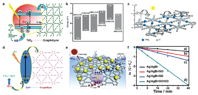
图11 石墨双炔与TiO2、ZnO和Ag3PO4复合材料的光降解性能及过程示意图:(a) P25-GDY的结构示意图和亚甲基蓝(MB)在P25-GDY上光降解的过程[82];(b) 不同TiO2-GDY复合材料的价带和导带位置[111];(c) GDY-NTNS[84]、(d) GDY-ZnO[85]、(e) Ag3PO4@γ-GY复合材料[86]的光催化机理示意图;(f) Ag/AgBr和石墨炔杂化体系在可见光照射下降解甲基橙的性能[89]Fig. 11 The performances and schematic illustrations of photodegradation process for graphdiynes combined with TiO2, ZnO and Ag3PO4[82,84-86,89,111].(a) Schematic structure of P25-GDY and tentative processes of the photodegradation of methylene blue (MB) over P25-GDY[82]; (b) CB, VB position of different TiO2-GDY composites[111]; Schematic illustration of photocatalytic mechanism for (c) GDY-NTNS[84], (d) GDY-ZnO[85], (e) Ag3PO4@γ-GY composites[86]; (f) Photocatalytic performances of Ag/AgBr, Ag/AgBr/GO, Ag/AgBr/GDY, and Ag/AgBr/GO/GDY toward the photodegradation of MO pollutant under visible-light irradiation[89]. Copyright 2012, Wiley-VCH; Copyright 2013, American Chemical Society; Copyright 2018, Springer; Copyright 2015, American Chemical Society; Copyright 2020, Elsevier; Copyright 2015, Royal Society of Chemistry |
3.2 光电催化电极
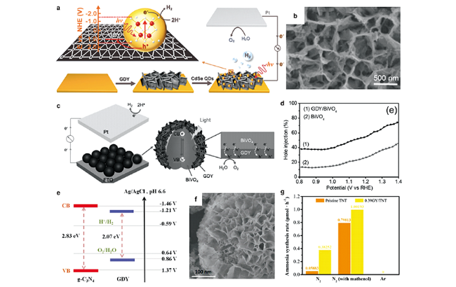
图12 石墨双炔基光电极的光生载流子转移机制示意图及形貌和性能[43,91,93,94,99]:(a) 由CdSe QDs/GDY光电阴极组成的PEC电池;(b) CdSe QDs/GDY薄膜的SEM图像[91];(c) PEC中GDY/BiVO4光阳极和光生激子在界面处的迁移示意图;(d) BiVO4 和 GDY/BiVO4 光阳极的空穴注入率[43];(e) g-C3N4和GDY的能带结构[93];(f) g-C3N4/GDY/NiFe-LDH结构的SEM图[94];(g) 不同条件下TNT 和 GY/TNT的氨合成速率[99]Fig. 12 The mechanism of photogenerated carrier transfer, morphology and performances of graphdiyne-based photoelectrode[43,91,93,94,99].(a) Schematic diagram of the PEC Cell, consisting of the CdSe QDs/GDY photocathode; (b) SEM image of the assembled CdSe QDs/GDY film[91]; (c) Schematic illustration of GDY/BiVO4 photoanodes in a PEC setup and the migration of the photogenerated excitons at the interface; (d) Hole injection yield of BiVO4 and GDY/BiVO4 photoanodes[43]; (e) Band structures of g-C3N4 and GDY[93]; (f) SEM image of the g-C3N4/GDY/NiFe-LDH structure[94]; (g) Ammonia synthesis rate of pristine TNT and GY/TNT sample under different condition[99]. Copyright 2016, American Chemical Society; Copyright 2017, Wiley-VCH; Copyright 2018, Wiley-VCH; Copyright 2020, Wiley-VCH; Copyright 2021, Elsevier |
3.3 光催化分解水
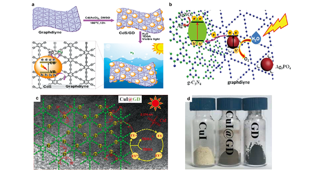
图13 石墨双炔基产氢光催化剂的制备及反应过程示意图:(a) CdS/GDY复合材料的制备及其光催化过程[101];(b) APO/GDY/CN Z-scheme系统可能的电子转移机制[100];GDY-CuI的(c) 析氢机理分析和(d)照片[103]Fig. 13 Schematic illustration of preparation and charge carrier transfer of graphdiyne-based photocatalysts for H2 evolution[100,101,103].(a) Preparation of CdS/GDY composite and its photocatalytic process[101]; (b) Possible electron transfer mechanism of the APO/GDY/CN Z-scheme system[100]; Hydrogen evolution mechanism analysis of (c) GDY-CuI and (d) their photos[103]. Copyright 2019, American Chemical Society; Copyright 2018, Elsevier; Copyright 2020, Wiley-VCH |
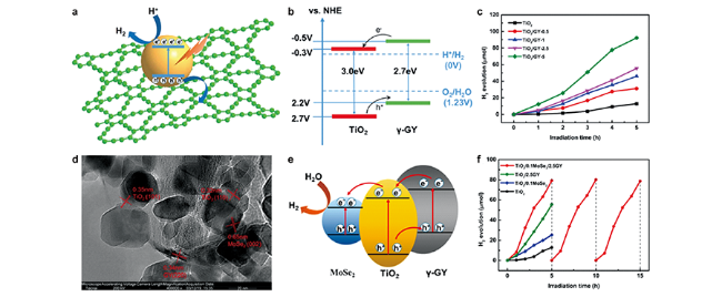
图14 TiO2/γ-GY的(a)光催化过程和 (b)能带结构示意图,以及 (c)产氢活性[66];TiO2/MoSe2/GY的(d)HRTEM图,(e)能带结构示意图和(f)产氢活性[67]Fig. 14 (a) Photocatalytic process, (b) band structure diagram and (c) hydrogen production activity of TiO2/ γ-GY composites[66]; (d) HRTEM, (e) band structure diagram, and (f) hydrogen production activity of TiO2/ MoSe2 /γ-GY ternary complex[67]. Copyright 2018, Royal Society of Chemistry; Copyright 2020, Springer |
3.4 光还原CO2
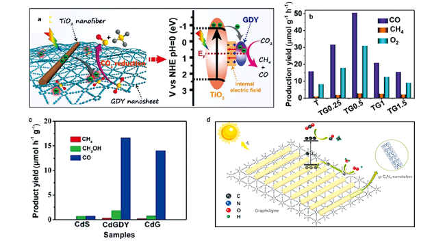
图15 GDY异质材料光催化还原CO2机理及性能:(a) TiO2/GDY 异质结示意图;(b) TiO2/GDY还原 CO2 的光催化活性[105];(c) 纯 CdS、CdG 和 CdGDY 光催化还原 CO2 活性[106]; (d) GDY@CNtb光催化还原CO2机理[107]Fig. 15 The mechanism and performances of photocatalytic CO2 reduction for graphdiyne-based heterostructures.(a) Schematic illustration of TiO2/GDY heterojunction; (b) Photocatalytic activities of CO2 reduction over TiO2/GDY samples[105];(c) CH4, CH3OH and CO evolution during photocatalytic CO2 reduction over pure CdS, CdG and CdGDY[106]; (d) Proposed mechanism of photocatalytic CO2 reduction over GDY@CNtb[107]. Copyright 2019, Wiley VCH; Copyright 2020, Royal Society of Chemistry; Copyright 2021, Elesevier |