


1 引言
表1 煤气化的主要反应Table 1 The main recation of coal gasification to produce hydrogen |
| Reaction type | Reaction equation | Reaction heat ΔH 298 K, kJ·kg-1·mol-1 | equilibrium constant | |||
|---|---|---|---|---|---|---|
| 800 ℃ | 1300 ℃ | |||||
| heterogeneous reaction | ||||||
| combustion | C+O2=CO2 | -406 430 | 1.8×10¹⁷ | 1.5×10¹³ | ||
| partial combustion | 2C+O2=CO | -246 372 | 1.4×10¹⁷ | 4.56×10¹⁵ | ||
| Carbon reacts with water vapor | C+H2O=CO+H2 | +118 577 | 0.807 | 1.01×10² | ||
| Boudouard reaction | C+CO2=2CO | +160 896 | 0.775 | 3.04×10² | ||
| hydrogenation reaction | C+2H2=CH4 | -83 800 | 0.466 | 1.08×10⁻² | ||
| homogeneous reaction | ||||||
| Hydrogen combustion reaction | 2H2+O2=2H2O | -482 185 | 2.2×10¹⁷ | 4.4×10¹¹ | ||
| CO combustion reaction | 2CO+O2=2CO2 | -567 326 | 2.4×10¹⁵ | 4.9×10¹⁰ | ||
| water-gas reaction | CO+H2O=CO2+H2 | -42 361 | 1.04 | 0.333 | ||
| Methanation reaction | CO +3H2=CH4+H2O | -206 664 | 0.577 | 1.77×10⁻⁴ | ||
2 传统化石燃料重整制氢
2.1 煤制氢
2.1.1 煤气化制氢
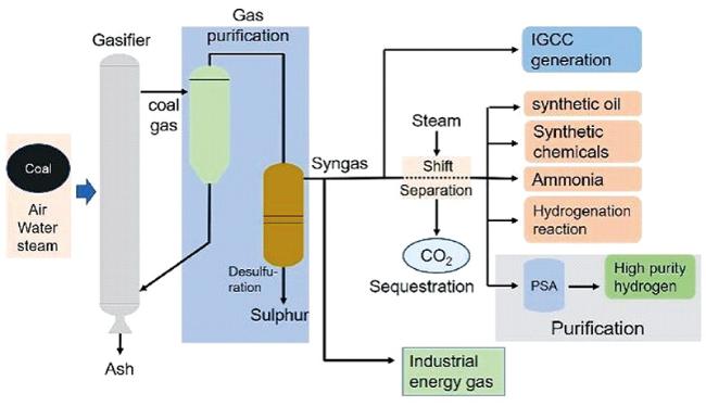
表2 四种常见气化炉的基本信息Table 2 Basic information of four common gasifiers |
| Shell gasifier[21] | GSP gasifier[22] | Texaco gasifier[25] | Tsinghua gasifier[24] | |
|---|---|---|---|---|
| Gasification form | Dry powder gasification | Dry powder gasification | Coal water slurry gasification | Coal water slurry gasification |
| Gasification conditions | High temperature and pressure | High temperature and pressure | High temperature and pressure | High temperature and pressure |
| Advantages | High suitability of coal; High gas production efficiency; Small oxygen production equipment; High power generation efficiency; Good environmental performance | Long life; Less investment in syngas reprocessing; Low investment; Gases are suitable for the manufacture of synthetic ammonia | Low methane content; High suitability of coal; Small operation risk; All sewage can be used to make coal water slurry; Simple structure, low operating cost; Simple ash removal system | High safety of ignition system; Obvious investment advantages; Wide adaptability of coal ;High gasification efficiency; Low operating cost; Water saving, environmentally friendly |
| Disadvantages | Large investment in equipment; Complex structure of gasifier and waste boiler | Low single furnace production capacity; The long-term operation effect is poor | High oxygen consumption; Narrow adaptability of raw materials; Refractory material has short life | - |
2.1.2 煤超临界水气化制氢
表3 几种典型天然气制氢反应器的主要特点对比[37]Table 3 Comparison of main characteristics of several typical hydrogen production reactors from natural gas[37] |
| Fixed bed | Fluidized bed | Membrane reactor | Plasma reactor | Solar reactor | Microchannel reactor | |
|---|---|---|---|---|---|---|
| Reactor structure | Relatively simple | Simple | Complicated | Complicated | Very complicated | Very complicated |
| Operation difficulty | Simple | Relatively simple | Complicated | Simple | Very complicated | Very complicated |
| Advantage | Easy operation; Low processing cost | Uniform distribution of temperature and concentration | Catalytic reaction and separation coupling; High conversion rate; High purity hydrogen | Strong adaptability of raw materials; good processing flexibility | Pollution-free | Large specific surface area, short transfer distance and low transfer resistance |
| Disadvantage | Fly temperature; Channel flow | Serious backmixing | Metal film is limited by high temperature durability; Non-metallic films are limited by selectivity | Poor selectivity; High energy consumption | Low energy utilization efficiency; High fluctuation due to weather influence | High number magnification cost; Poor uniformity of fluid distribution in parallel operation |
2.2 天然气制氢
2.2.1 SMR的基本原理
2.2.2 SMR的催化剂
表4 不同条件下通过实验或理论计算得到的催化剂活性顺序Table 4 The sequence of catalyst activity obtained by experimental or theoretical calculation under different conditions |
| Catalytic activity | Carrier (Theoretical calculation) | External environment | ref |
|---|---|---|---|
| Rh, Ru > Ni, Pd, Pt > Re > Ni0.7Cu1.3 > Co | Al2O3 or MgO | 500 ℃, 1 bar | Rostrup-Nielsen[50] |
| Rh-Ru > Ni > Ir > Pd ~ Pt >> Co ~ Fe | - | 350 ~ 600 ℃, 1 bar | Kikuchi et al.[51] |
| Pd | MgO | 550 ℃, 1 bar | Rostrup-Nielsen et al.[52] |
| Ru > Rh > Ir > Pt > Pd | MgO | 600 ~ 900 ℃, 1 bar | Qin et al.[53] |
| Ni | ZrO2/CeO2, Al2O3 | 600 ℃ | Wei and Iglesia[54⇓⇓⇓~58] |
| Ru ~ Rh > Ni ~ Ir ~ Pt ~ Pd | ZrO2, Al2O3, MgAl2O4 | 500 ℃, 1 bar | Jones et al.[59] |
| Ru > Rh > Ni > Ir > Pt ~ Pd | Theoretical calculation | 500 ℃, 1 bar | Jones et al.[59] |
| Rh > Pt > Ni | Theoretical calculation | 600 ℃, PH2O-0.25 bar, $P_{H_2}$-0.4 bar, PCO-0.2 bar, $P_{CH_4}$-0.2 bar | German et al.[43] |
| Pt > Ni > Rh | Theoretical calculation | 600 ℃, $P_{H_{2}O}$-0.25 bar, $P_{H_2}$-0.4 bar, PCO-0.2 bar, $P_{CH_{4}}$-1.5 bar | German et al.[43] |
3 工业副产氢
3.1 变压吸附法
3.2 低温分离法
| Volume fraction (%) | P(MPa) | ||||||||
|---|---|---|---|---|---|---|---|---|---|
| H2 | CH4 | CO | CO2 | N2 | H2S | O2 | Cl2 | ||
| Coke oven gas | 55 ~ 60 | 23 ~ 27 | 6 ~ 9 | - | 2 ~ 5 | 0.5 ~ 3.0 | - | - | ~0.03 |
| Methanol exhaust | 50 ~ 60 | 20 ~ 25 | 5 ~ 10 | 10 ~ 15 | - | - | - | - | 5 ~ 7 |
| Synthetic ammonia tail gas | 50 ~ 60 | 15 ~ 20 | - | - | 15 ~ 20 | - | - | - | 10 ~30 |
| Exhaust gas from chlor-Alkali industrial (after alkali washing) | ~98 | <2 ppm | 29 ppm | 700 ppm | 195 ppm | - | 1.34 | 10~20 ppm | 0.1~0.6 |
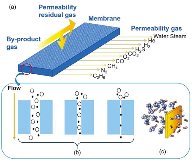
3.3 膜分离法
3.4 金属氢化物分离法
表6 不同工业氢气分离方式的不同指标对比[63,87]Table 6 Comparison of different indicators of different hydrogen separation methods[63,87] |
| Cryogenic separation | Organic membrane separation | PSA | |
|---|---|---|---|
| Scale (Standard conditions) (m3·h-1) | 5000 ~ 100 000 | 100 ~ 64 900 | 10 000 ~ 500 000 |
| Operating pressure(MPa) | 1.0 ~ 8.0 | 10.0 ~ 15.0 | 0.5 ~ 6.0 |
| Feed pressure(MPa) | 1.0 | 0.2 ~ 0.5 | 1.0 |
| Minimum hydrogen content of raw gas(%) | 30 | 30 | 50 |
| Preprocessing requirement | Removing H2O、CO2、H2S | Removing H2S | No requirement |
| Purified hydrogen volume fraction(%) | 90 ~ 95 | 80 ~ 99 | > 99.99 |
| Hydrogen recovery(%) | 98 | 95 | 85 |
| Relative investment expense(thousand) | 20 ~ 30 | 10 | 10 ~ 30 |
| Elasticity of operation(%) | 30 ~ 50 | 30 ~ 100 | 30 ~ 100 |
| Expansion difficulties | Very difficult | Very simple | Simple |
4 清洁能源电解水制氢
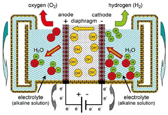
4.1 碱性电解池
4.1.1 关键电极材料
表7 不同电解效率的计算形式及含义[99]Table 7 Calculation forms and meanings of different expressions of electrolytic efficiency[99] |
| Calculate formula | Explain | Supplement | |
|---|---|---|---|
| Electrolytic efficiency | $η_{V}=\frac{E_{O_2}-E_{H_2}}{E} \times 100\%$ | The ratio of effective voltage of electrolysis to total voltage | The electrolytic efficiency described by balancing electromotive force and electrolytic voltage is a common way to measure the electrolytic efficiency of hydrogen production system |
| Faraday efficiency | $\eta_{\Delta G}=\frac{\Delta G}{\Delta G+Losses}=\frac{E_{\Delta G}}{E}$ | The ratio of the theoretical energy of electrolytic water to the actual input energy | $\eta_{25 ℃}=\frac{1.23V}{E}$ |
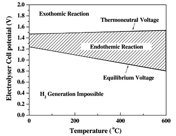
| Thermal efficiency | $\eta_{\Delta H}=\frac{\Delta H}{\Delta G+Losses}=\frac{E_{\Delta H}}{E}$ | The proportion of the actual electrolytic energy that is input to maintain heat balance | $\eta_{25 ℃}=\frac{1.48V}{E}$,1.48 is the electrolytic voltage when thermoneutral, and the thermal efficiency is 100% when E is equal to 1.48. The thermal efficiency can be higher than 100% when external heating is provided |
| Hydrogen production efficiency | $\eta_{H_2}=\frac{283.8(kJ)}{Uit}$ | The ratio of the energy generated by 1g of hydrogen to the total energy input | The calorific value of hydrogen is 283.8kJ/g, U is the electrolytic voltage, i is the current, and t is the time required to produce 1g hydrogen |
| Net efficiency | $\eta_{Loss}=1=\frac{E_{Loss}}{E_{input}}$ | 1 minus the energy lost as a percentage of the total energy | $E_{Loss}=\eta+iR_{cell}$ |
表8 电流密度为100 mA/m2的不同氢电极材料电解参数Table 8 Electrolytic parameters of different hydrogen electrode materials with current density of 100 mA/m2 |
| T(℃) | Concentration of KOH | Overpotential(mV) | Preparation methods | ref | |
|---|---|---|---|---|---|
| NiCu | Room temperature | 6 M | -370 | Electrodeposition | Sang et al.[107] |
| Dense NiCu | 35 | 6 M | -500 | Arc fusion | Yu et al.[108] |
| Sintered Porous Ni-Cu | 35 | 6 M | -400 | Powder metallurgy | Yu et al.[108] |
| Metallurgical NiCu | 25 | 6 M (NaOH) | -300 | Powder metallurgy | Wang et al.[109] |
| Smooth NiCo | 25 | 6 M | -380 | Electrodeposition | Fan et al.[110] |
| NiCo | 25 | 6 M | -430 | Electrodeposition | Hong et al.[111] |
| Ra-Ni from Al | 22 | 6 M | -115 | Pressing sintering | Brennecke et al.[112] |
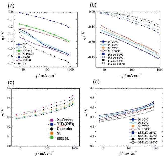
图7 不同氢电极和氧电极材料超电势随电流密度变化的关系曲线。(a), (b)氢电极;(c), (d)氧电极;(a), (c)T=30 ℃;SS316L:不锈钢(Cr17Ni12Mo2)圆盘电极;Ra-Ni:兰尼镍(Raney Ni,具有高内表面积的多孔镍);电解质溶液:KOH,6 mol/L[106]Fig.7 Relationship curve of superpotential with current density of different hydrogen electrode & oxygen electrode materials. (a), (b): Hydrogen electrode; (c), (d): oxygen electrode; (a), (c): T=30 ℃; SS316l:Stainless steel (Cr17Ni12Mo2) disk electrode; Ra-Ni:Raney Ni (Raney Ni, porous nickel with high internal surface area); Electrolyte solution:KOH, 6 mol/L[106] |
4.1.2 电解池结构设计
4.1.3 AEC堆的发展现状
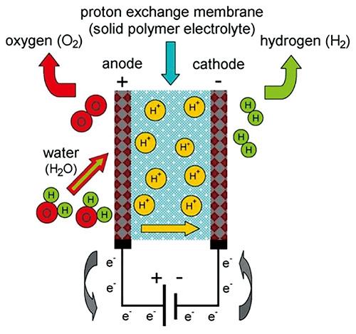
4.2 质子交换膜电解池
4.2.1 关键电极材料
4.2.2 电解池关键结构
4.2.3 PEMEC堆的发展现状
4.3 固体氧化物电解池
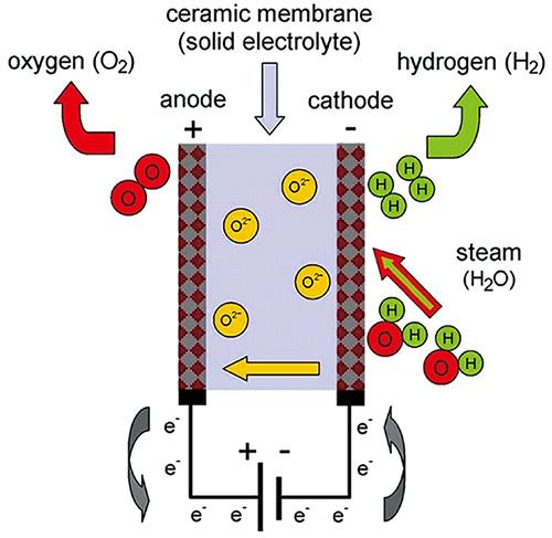
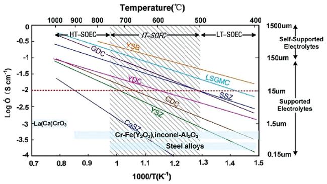
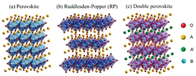
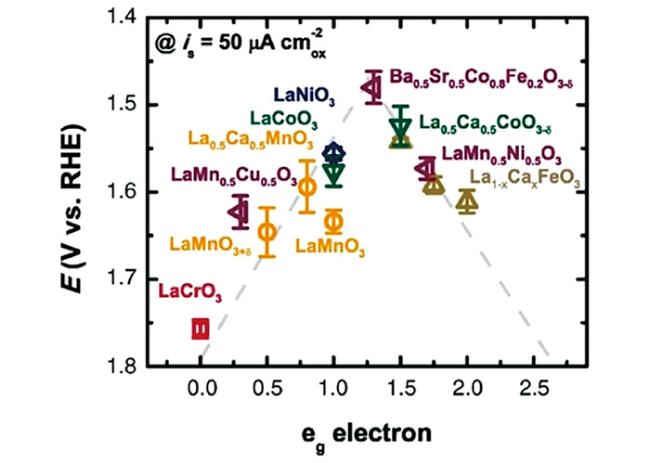
4.3.1 关键材料
4.3.2 电解池结构优化设计
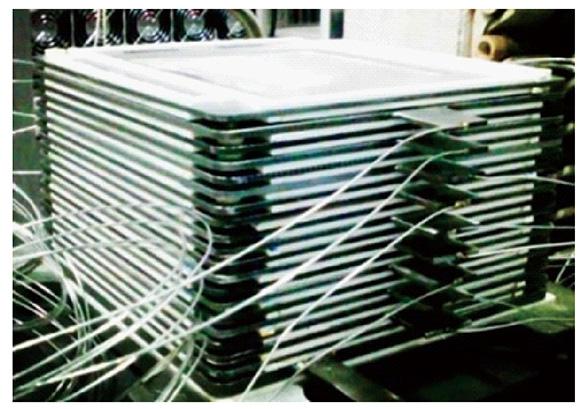
4.3.3 SOEC堆发展现状
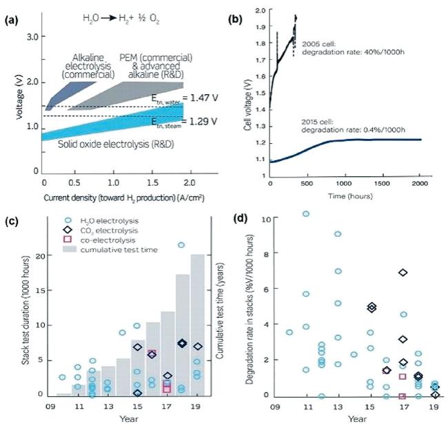
图14 近15年SOEC和SOEC堆的技术进展:(a)不同电解池初始性能比较;(b)SOEC单体衰减性能的提升;(c)SOEC堆测试时长进展;(d)SOEC堆衰减性能的提升[4]Fig.14 Technical progress of SOEC and SOEC stack in recent 15 years: (a) Comparison of several typical hydroelectrolysis technologies; (b) SOEC monomer attenuation performance improvement; (c) SOEC stack duration tests progress; (d) the corresponding degradation of SOEC stack[4]. Copyright 2020, AAAS |
5 其他制氢新技术
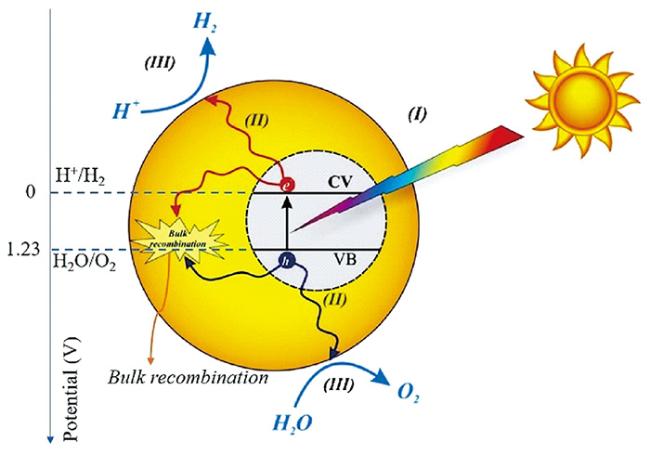
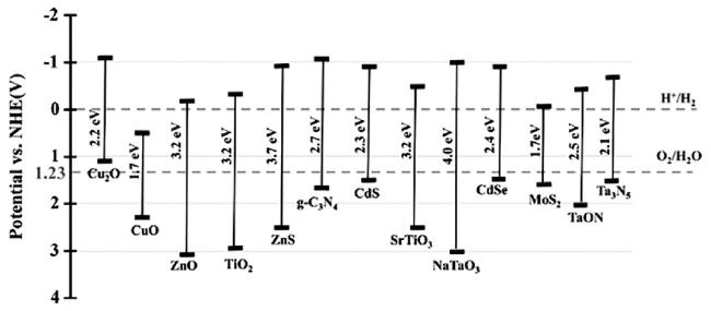
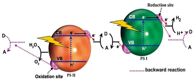
5.1 太阳能光解制氢
5.2 生物质发酵制氢
5.3 生物质热化学转化制氢
5.4 热化学循环制氢
6 不同制氢方式比较
表9 主要制氢工艺的基本信息比较Table 9 Basic information of major hydrogen production process |
| Hydrogen production process | Raw material | Technology maturity | Energy conversion efficiency (%) | Cost (/Yuan·kg-1) | CO2 emission (kg CO2/kg H2) | ||
|---|---|---|---|---|---|---|---|
| Fossil fuel reforming | Coal gasification | Coal | Mature | ~47[62] | 6~10[10] | 11~25[10] | |
| Coal gasification +CCS | Coal | Completing pilot scale test | - | 12~16[10] | 2~7[10] | ||
| Coal supercritical water gasification | Coal, water | Completing pilot scale test | ~60a[31] | ~8[36] | ~0[10] | ||
| SMR | methane | Mature | - | 9~18[10] | 8~16[10] | ||
| Industrial by-product of hydrogen | Industrial exhaust | Mature | - | 10~16[10] | - | ||
| Electrolysis of water | Grid electricity/AEC | Water | Mature | ~25[133] | 30~40[10] | ~45[10] | |
| Renewable energy sources electrolyze water | AEC | Water | Mature | ~25[133] | 18~23[10] | 1~3[10] | |
| PEMEC | Water | Relatively mature, Early industrialization | ~35[133] | ≤62[191] | 1~3[10] | ||
| SOEC | Water | demonstration works | 52 ~ 59[133] | - | 1~3[10] | ||
| Abandoned electric from Renewable energy sources electrolyzes water | Water | Demonstration stage | - | ~10[10] | 1~3[10] | ||
| Other new technologies for hydrogen production | Solar energy photolysis water | Water | Laboratory stage | <10[182] | - | ~0[10] | |
| Biomass fermentation | Biomass | Demonstration stage | 10~40[188]b | - | ~0[10] | ||
| Biomass gasification | Biomass | Mature | 35~50[197] | ~16[191] | 0.4~5.6[198] | ||
| Thermochemical cycle | Water | Laboratory stage | ~38[198] | ~18[191] | 0.3~0.86[198] | ||
a: Coal-electricity conversion efficiency of coal supercritical water gasification thermal cycle power generation system b: The efficiency of hydrogen production from biomass fermentation is usually expressed by hydrogen production rate,The hydrogen production rate of previous studies is 1 ~ 3.9 mol H2/(mol glucose)[188],According to the formula: $Energyconversionefficiency=\frac{Hydrogenproductionrate \times Q_{calorificvalueofhydrogen}} {Q_{calorificvalueofglucose}}$ The data in the table can be estimated. |